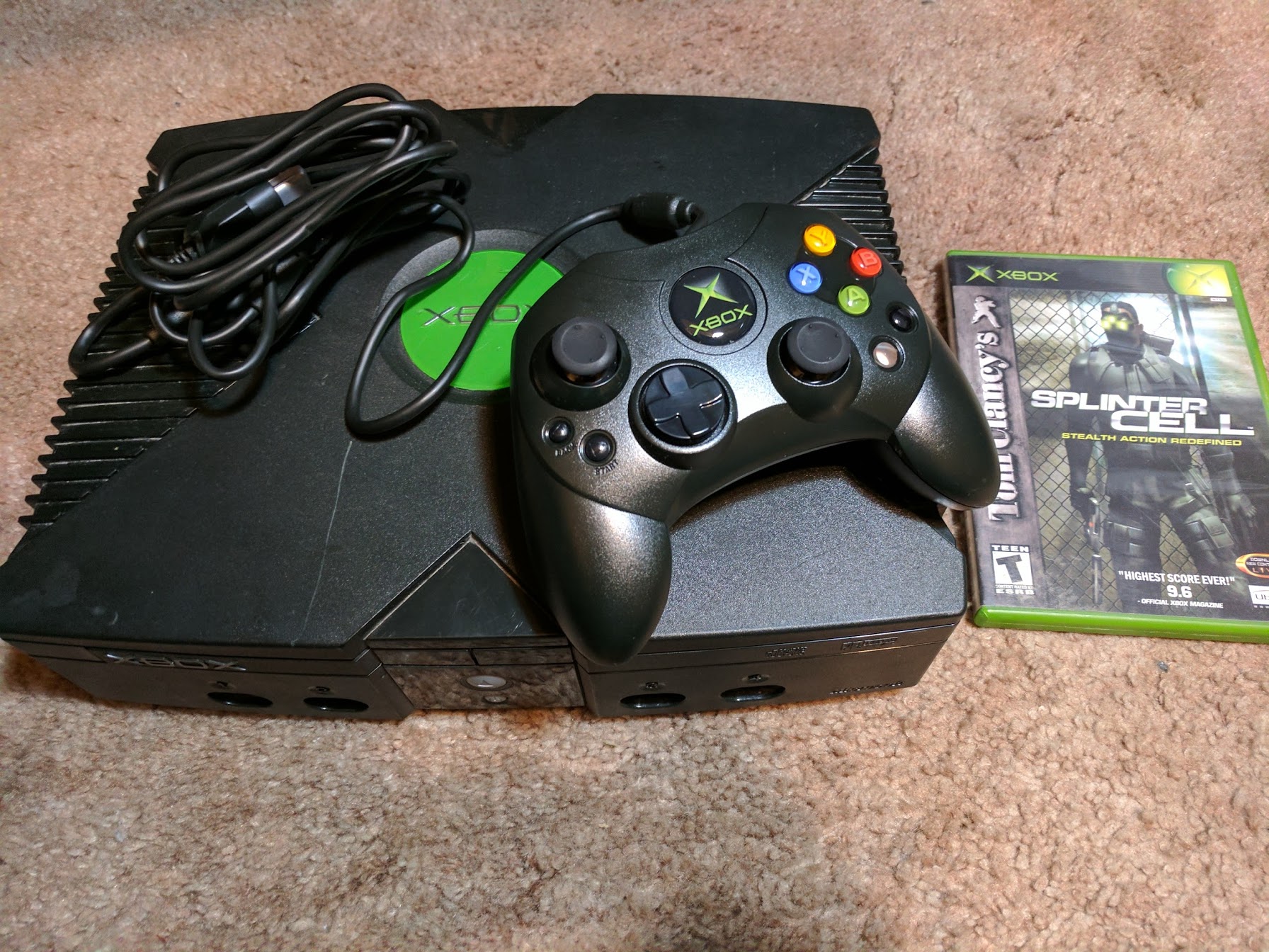
Original Xbox 128MB RAM upgrade
A couple years ago I attempted to upgrade the RAM in an original Xbox from 64MB to 128MB. That attempt wasn’t a success. More recently I tried the original Xbox 128MB RAM upgrade again, this time successfully. This post covers the process of upgrading the RAM in the original Xbox. I cover what I did wrong with my first attempt, and how I was able to successfully upgrade the RAM with my second attempt.
What’s the point of upgrading the RAM?
The truth about upgrading the RAM in an original Xbox is that it isn’t incredibly useful. You don’t really see any benefits while playing retail games or anything like that. There are however some benefits of upgrading the RAM.
- There are some Sega Chihiro arcade games that work on original Xbox consoles with 128MB of RAM. Those games include:
- Crazy Taxi High Roller
- Ghost Squad
- Gundam Battle Operating Simulator
- Ollie King
- Outrun 2
- Sega Club Golf 2006 Next Tours
- Sega Network Taisen Mahjong MJ 2 and 3
- The House of the Dead III
- Virtua Cop 3
- Ford Racing Full Blown
- Wangan Midnight Maximum Tune 1 and 2
- Many emulators on original Xbox can take advantage of 128MB of RAM
- Game debugging performance is improved (Xbox development kits had 128MB of RAM).
So an original Xbox 128MB RAM upgrade isn’t quite as useful as a hardmod or softmod for the system. It’s more of a mod for those who want to try out those Sega arcade games, run additional emulators, or get into Xbox game development.
Things you’ll need
There are several ways to perform this upgrade. This is a list of the things I used to upgrade my console.
- A hard modded original Xbox console
- Four extra RAM chips (can be sourced from another console, or from China)
- Soldering iron (I use a Hakko FX-951, but cheaper T12 tip compatible irons exist, and even some of the more generic temperature controlled irons should work).
- Soldering iron knife tip (I used a T15-KU)
- Hot air rework station (if you are sourcing RAM chips for another console, or run into issues and would like to remove the additional RAM from your console)
- No clean flux (liquid or gel type)
- Solder wick
- Solder
- Tweezers
- Magnification
- Isopropanol
Step 0. Sourcing original Xbox RAM chips

To upgrade the RAM in your original Xbox you’ll need to get your hands on four extra RAM chips. There are two main ways to do this.
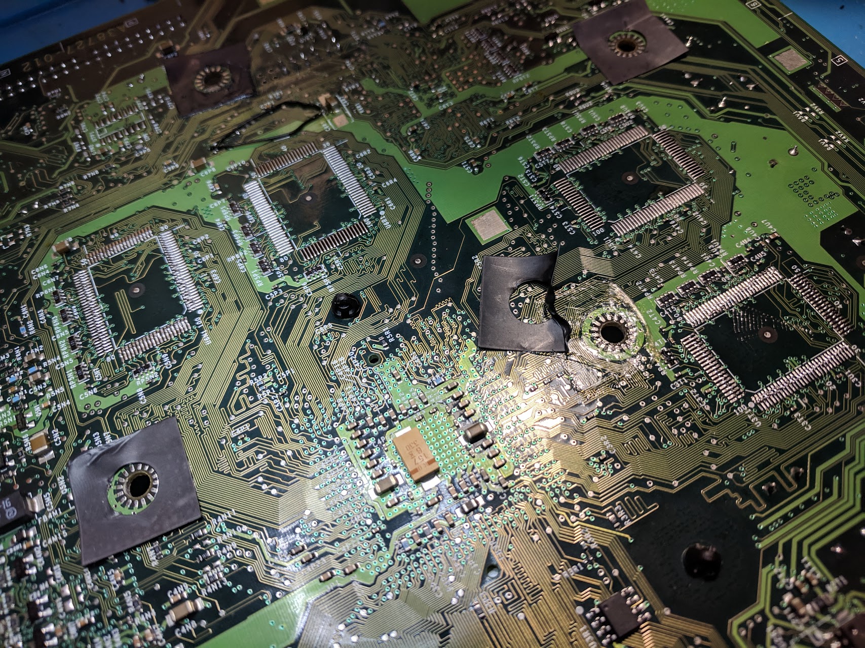
The first way to get extra RAM chips is to remove them from another original Xbox board. This is what I did because I already had a broken original Xbox board. The downside of this method is that you need to sacrifice an original Xbox, and that there’s a chance the RAM will be damaged if you heat it up too much while desoldering it.
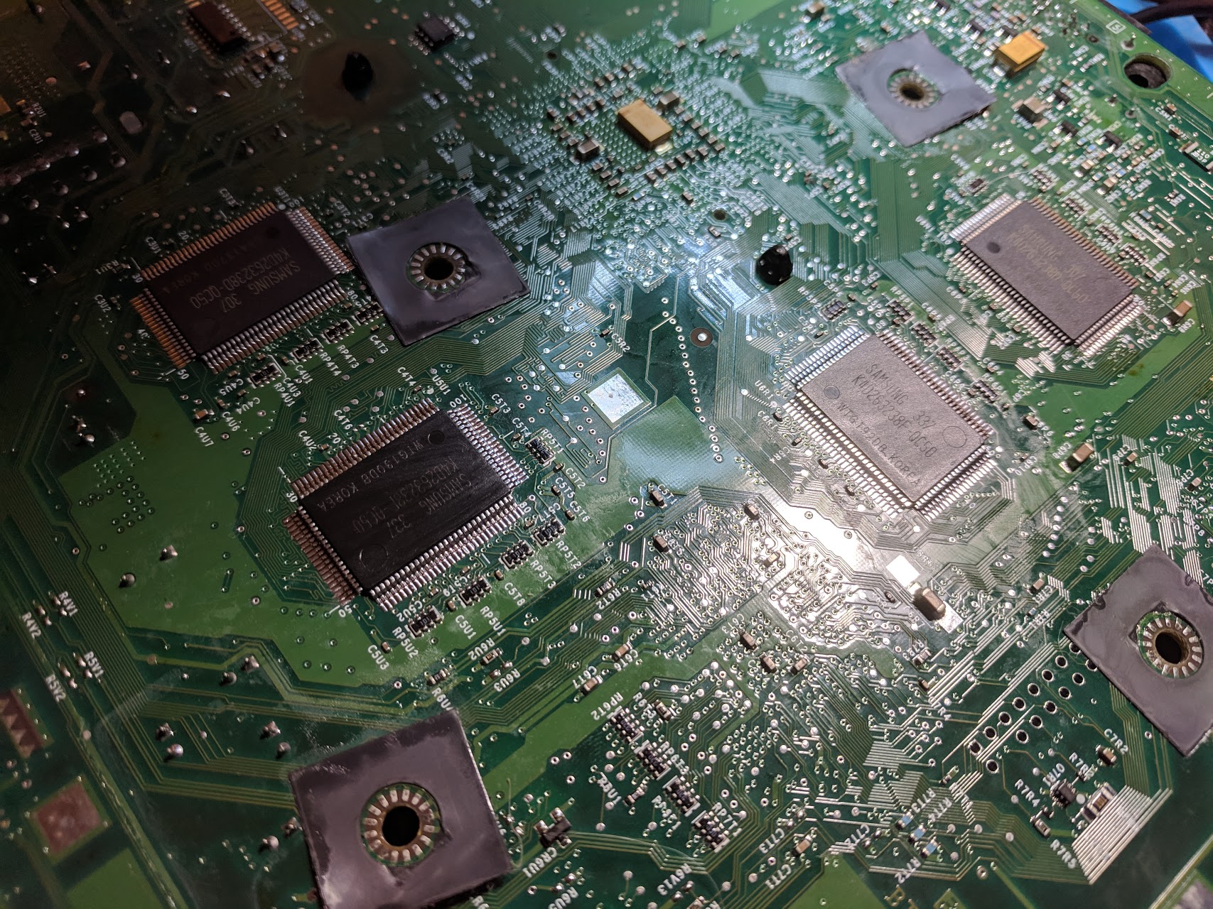
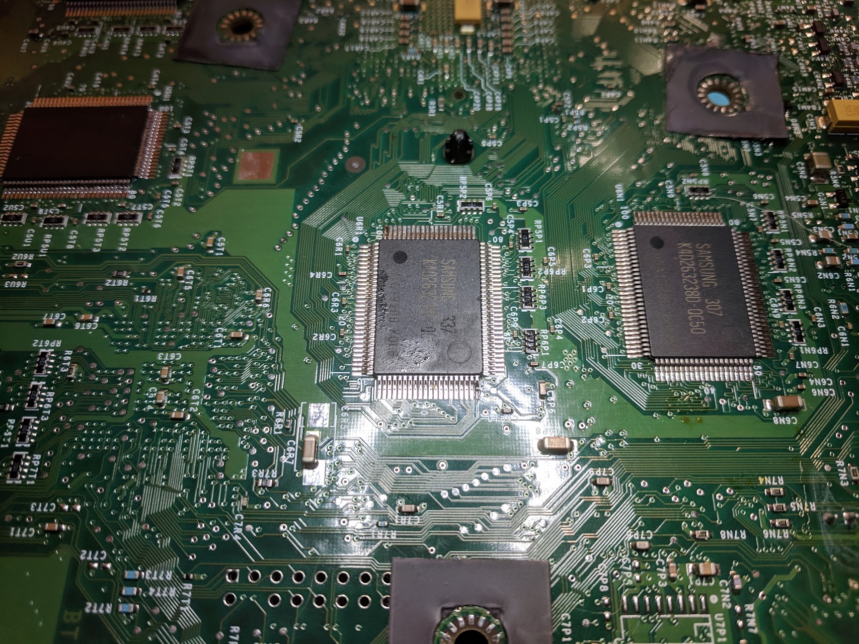
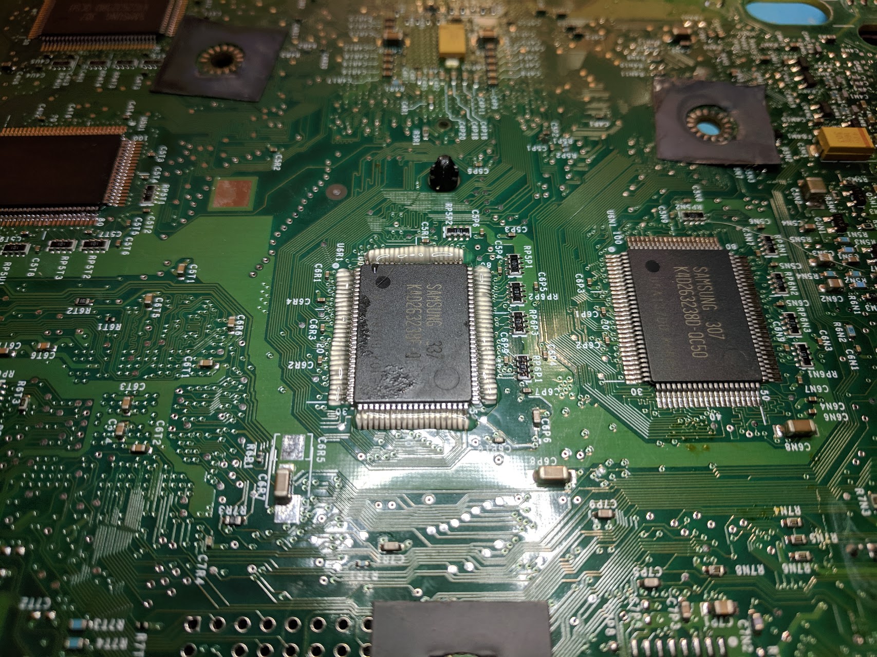
From my understanding all of the RAM from any original Xbox is compatible with any other original Xbox. In my case I was able to put Samsung K4D263238F-QC50 RAM into a system that originally had Samsung K4D263238D-QC50 RAM.
Removing RAM from an original Xbox is pretty simple. Just heat up the pins of the RAM chip with a hot air rework station, then remove the chip when the solder melts enough. Using flux can help, but it isn’t really necessary.
The other way to get extra RAM chips is to purchase them from the internet. I don’t know any US suppliers that supply compatible RAM chips at a decent price, but there are tons of Chinese suppliers that do. Just search a place like eBay or AliExpress for the model number of the RAM chips that are inside your console.
Step 1. Installing XBlast OS for RAM chip testing
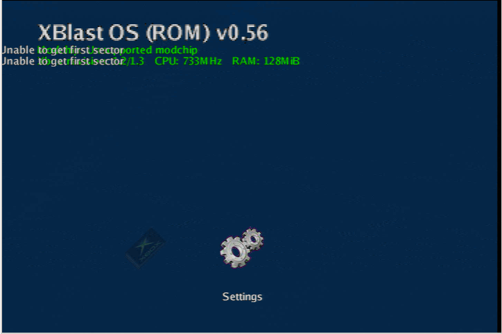
This is a very important step if you want your installation to be less frustrating. I didn’t do this the first time I attempted to upgrade the RAM, but did the second time. Basically what you need to do is install the XBlast OS BIOS onto your system. This BIOS allows you to boot with any number of RAM chips installed, and allows you to test each chip individually.
A normal Xbox BIOS will only boot with exactly 4 or exactly 8 perfectly installed RAM chips. With XBlast OS as long as you don’t have any serious shorts you’ll be able to boot. Meaning that you’ll be able to install a single chip and test it before moving on to the next chip. That removes a lot of guess work and troubleshooting and makes things so much easier.
I’m not going to explain how exactly to install XBlast OS. Here’s a link to the XBlast OS project page. If you’ve ever flashed a BIOS to your Xbox before it’s pretty much the same process. There’s a crcwell.bin file in the OS zip file which you can flash to your BIOS chip.
Note that XBlast OS isn’t something you’ll want to keep on your Xbox once you’re finished upgrading the RAM. At the moment it has very limited functionality and can’t play original Xbox games. So you might want to take a dump of your BIOS so it’s easier to flash it back when done.
Step 2. RAM chip installation
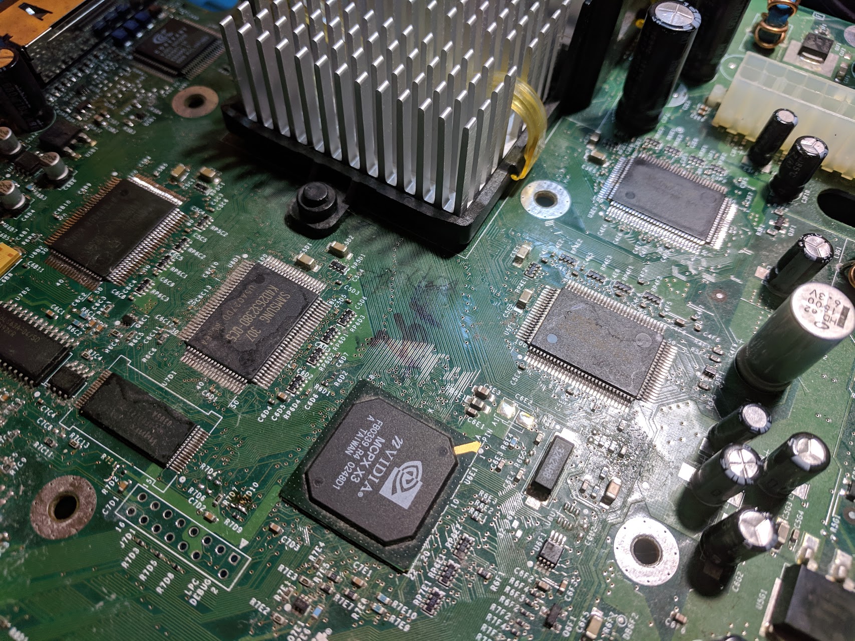
In its default configuration the original Xbox will have two RAM chips on the top side of the board, and two on the bottom side of the board. To upgrade the RAM you’ll need to solder two chips onto the top, and two chips onto the bottom. You can install them in any order, but I found the chips on the bottom to be easier to install because there weren’t any components like capacitors or heatsinks in the way. So you might want to start on the bottom and work your way up.
The process of installing each chip is pretty much the same, so I’m just going to cover installing a single chip. Just repeat steps 2 and 3 for each of the four chips.
Some boards already have a small amount of solder applied to the RAM chip pads. My board didn’t, but if it did there would be a fairly obvious small bump in each pad. If there is you can choose whether or not you’d like to remove it using solder wick. Just be careful not to apply any pressure, or use too much heat, since you risk ripping off a pad.
Next you’ll want to align the RAM chip in its correct orientation. Each chip should have the same orientation as the chip right next to it. With my chips there is also a smaller circle engraving on the chip that aligns with the corner with a small white circle on the silkscreen of the Xbox board.

With the RAM chip aligned you’ll want to pre-tin one corner pad of the board with a little bit of solder. Then put the RAM chip back on top of the board making sure to align it over top of the pads as closely as possible. Then you can solder that one corner pin to the pre-tinned pad.
Recheck the alignment and make any adjustments if needed. You can make very small adjustments without needing to heat up the solder in the corner. Bigger adjustments will require heating up the solder in the corner. I find that keeping a finger pushed down on the chip during this whole process is useful in keeping things centered. Once the chip is fully aligned solder the opposite corner pin to the pad.
Now you can solder the rest of the pins to the board. Apply flux to all of the pins, don’t worry about applying too much, the more the better. Once the flux is applied carefully apply a small amount of solder to the tip of your soldering iron, and drag it across the pins. You’ll want to both drag across the pins from pin to pin, as well as drag down the pins from the top of the pin down to the edge of the pad. I did the dragging process in both directions several times before it was the way I wanted.
The goal is to apply an even coating of solder to each pin that forms a nice solid connection with the pad. It’s better to use not enough solder and add more later than it is to apply too much solder and have a hard time removing it. If you add too much solder it may work itself out as you repeat the dragging process focusing on bridged or cold connections. If it doesn’t you may need to use a little bit of solder wick to remove some solder.
Repeat this process for each of the four sides of the chip. You’ll likely start to get a feel for how much solder each side needs as you get more practice. Once you think the RAM chip is properly soldered move on to the RAM chip testing phase.
Step 3. RAM chip testing
Once you’ve installed a RAM chip you’ll want to test it. Before you do that you’ll want to clean off as much flux as you can using isopropanol and a brush. Then you can put the board into the console. You don’t need to connect everything, just the power supply connector, power button connector, and controller port connectors. Then you can plug in the power supply into an outlet, and the console into a TV.
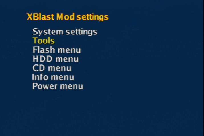
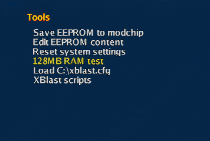
Turn on the console and you’ll see the XBlast OS boot menu. If you don’t then chances are you caused some sort of short on the board that needs to be fixed. Select the settings menu, then select tools, then select the 128MB RAM test.
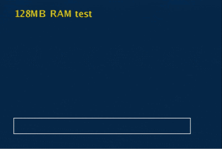
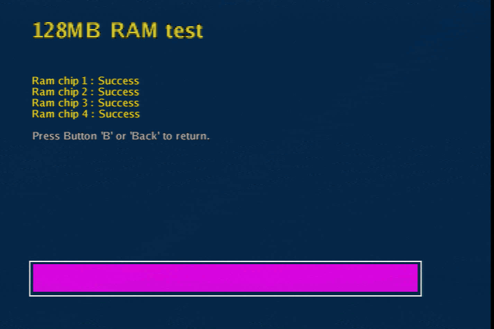
The 128MB RAM test tool will go through each RAM chip and test it. It may take a while, especially when you’ve installed all four chips. It will either say success or failed for each chip. If the test fails for the chip you are trying to install then you’ll need to rework it. If it succeeds you can move on to installing the next chip.
I had to rework the first RAM chip I installed, but was able to get the others working on my first try. A good way to diagnose the chip is to use tweezers and try to wiggle each pin (you can also sort of just run the tweezers along the pins and feel out any movement). If a pin wiggles or moves in any way it’s loose and needs to be soldered. You might also want to look around for any potential solder bridges and correct them. If you aren’t having any luck at all you might want to try reapplying flux to all of the pins and reflowing them with your soldering iron again.
Step 4. Finishing up the Xbox 128MB RAM upgrade
Once all four RAM chips have been tested you can completely put back together your system. You’ll want to reflash your BIOS of choice, but make sure it supports 128MB of RAM (most of the more modern ones do, but you should double check).
What I did wrong the first time
A couple years ago when I first tried to upgrade the RAM in the Xbox I didn’t have any luck. The system wasn’t able to boot no matter how many times I tried to rework the RAM chips.
One of the key things I didn’t do was use XBlast OS and test each RAM chip as I went. This is super useful since it isn’t an all or nothing installation. If a single chip doesn’t work you can see that and rework just that single chip. It removes a lot of the guess work.
The other problem I ran into was just not using the right tools, primarily from a lack of experience. I attempted to use a heat gun to reflow the RAM chips onto the existing solder on the board. In theory this should work, but it didn’t. A hot air rework station would have been a better tool for that method since it would allow a more focused flow of heat.
I found that the drag soldering method really is the ideal method for upgrading the RAM in an original Xbox.
Conclusion
By using drag soldering, and XBlast OS, upgrading the RAM in an original Xbox is actually a fairly quick and easy process. To be honest the benefits of having more RAM aren’t great, but it’s still a fun project if you have some spare time and want to fill those empty RAM pads on your console’s main board.
I’m wondering if you installed the N64 Amp with the mindset that it would be using TTL Sync or 75Ohm with termination? When I look at the mod, it’s almost as if it’s for TTL Sync, since it’s missing the 75OHm termination at R43. Did you bridge this connection instead and go with TTL Sync? I’m a little confused because you mentioned that you weren’t using the built in Amplifier in the 64, which makes sense.. but wouldn’t it require 75Ohm termination unless you used the built in Amp? I’m trying to do the same mod but I’ve botched a… Read more »
Those boards in the pictures were ones I was using to test some component values, so you can kind of ignore them. This image shows the final components for a board with 75 ohm CSYNC: The BOM lists all of the component values for both TTL and 75 ohm setups, and the readme lists different component values based on the console you are installing the amp into. R1 is required in both configurations. Both the 75 ohm and TTL versions of the board work. Just make sure whatever cables and receiving devices you are using are set up to properly… Read more »
Thanks, I have a straightforward converter box for 720p/1080p. I’ve done this mod with a Console5 kit successfully, this one is a bit more complicated. I’ll try it using 75ohm termination, a few more questions first. I noticed you jumped J1, but I didn’t see that noted in the ReadMe anywhere. Also do you remember if the top 4 caps beside R43 are the small 47pF caps (C14, C24 & C34?) The board isn’t marked well and I just want to be sure I’m not messing it up, thank you
Closing J1 disables the low pass filter in the THS7374. Those capacitors at the top are 47pF.
I purchased a few of these amps in case I ran in to trouble, I’m new to hot air technique for small PCBs. For the pictured board you showed, you left J2 open? Not having much luck with this Amp even though all the parts seem OK. TTL C-Sync would only be used if I was running C-Sync directly off the chip, but I’m running for R16 instead, so the 75Ohm termination should work for me. Unless I’m missing something in regards to how you choose to use C-Sync or not. I’ve heard some boards have C-Sync directly integrated to… Read more »
Yes, J2 is left open.
This guide covers some components that may need to be removed from the N64 board in order to use the CSYNC on the amp board: https://www.retrorgb.com/n64rgbmod.html
Thanks, my 64 doesn’t have those components which would create a direct C-Sync to multiout so I guess it isn’t designed for TTL. I tried my second board and I get the same result, I get a screen for about 1 second and then it goes black. Looking over the BOM, I’ve used the 1.2KOhm resistors for dimness on R11,21 &31. Doesn’t say it’s recommended for 64’s so I’m wondering if that was a bad idea. Otherwise I’m stumped, all components seem OK and tested. Using 75 Ohm termination as suggested, J2 is open etc. THS7314 connections test OK. ..… Read more »
These are what I use and it works with both the SNES Jr. and N64. I’d make sure the cable you are using isn’t messing things up and dropping the voltage below what it should be. An oscilloscope is a great tool to make sure everything on the output side is correct. 1x THS7374 (U1) 1x 0.1uF (C1) 1x 4.99k (R1) 3x 0.082uF (C11, C21, C31) 3x 5.1M (R12, R22, R32) 4x 75 (R13, R23, R33, R43) 4x 47pF (C14, C24, C34, C44) 3x 1.2k (R11, R21, R31) 1x 9.53k (R41) 1x 620 (R42) 1x 330uF (C43) That soldering also… Read more »
Thanks for your list, the only differences I see are at R1/R41, you’re using what’s recommended for TTL Sync (or close to it, 10.7Ohm is recommended, you have 9.53Kohm). I’m using 4.7Kohm there. Also the 680Ohm is recommended at 470Ohm, you’re using 680Ohm which I’m sure works fine as well. Regardless if I hook up my System with the SCART or just composite the same issue occurs (quickly on then off), I can rule out the SCART cable since it isn’t terminated with 75Ohm or any capacitors. I’ll reflow everything tonight and see how it turns out.
Well I tried the reflow with hot air and had much better results, overall a very clean board now. I’m still having the same issue unfortunately. Nothing seems out of sorts, so it narrows things down to two possibilites: – Maybe the designers just got the pcb design wrong – Or from the link here you mentioned: https://www.retrorgb.com/n64rgbmod.html There’s surface mount components that need removing. Mine didn’t have anything surface mount, I’ve thought of cutting the trace to pin 3 anyways for good measure, any idea if that would be a bad idea? The problem seems to be in the… Read more »
The board is definitely designed correctly. Do you happen to be installing it into one of the newer systems that doesn’t support the simple RGB bypass boards?
I’ve installed it in to a 64 with the VDC-NUS A chip, so it should work. It seems like something is shorting the C-Sync out since the signal drops once the board is installed.. if this 64 has C-Sync directly to multi out that might make sense, but as I’ve mentioned there’s no components at C22 on the 64. There is a direct closed circuit between Pin 3 and the capacitor beside R16, which is why I’m concerned there’s interference there.
You could try cutting that trace, or removing the components related to the sync signal from the amp circuit and use the console’s sync.
Well I tried removing the components for a straight cync signal but no luck. I noticed when I take off R43 (the big cap) the modchip is soundless, but when I have it in for 75Ohm termination I get a loud sound for small components. The sound happens right when the video dies out, after a few seconds.
The components themselves make noise? None of the components on the amp board should be making any noise.
I think it’s just the large cap making a noise, it’s odd but yes it’s coming from the amp. If I take the amp out, there’s no noise and I get regular multi-out. With the amp in, multi out doesn’t work on composite either.
I’m going to redo the board again. One question, you mentioned C1 in your list as 0.1uf, but you didn’t mention C2. C2 is listed as 22uf 6.3V with a tantalum capacitor, it is necessary I’d guess? I’m getting a few awkward on board readings at the 47pf caps but the rest of the board seems on point.
C2 is required, I must have just missed it when typing my list.
Got around to a new board, I tried it in my PCE instead. This time the cap at C2 (22uF) decided to fry and start smoking. I checked all connections on board before installing it, seemed fine. Have you tried it yet on different systems?
I’ve only done SNES and N64 consoles with that particular board. It is a fairly generic design that can be modified to work with other systems though.
I didn’t do any modifications, I’ll try it again on a 64 instead.
Other than using the Multi AV out for the RGB Outputs with C-Sync, Ground and 5V on the Borti board, I’d be lost on what type of other modifications would be needed for the PCE. I had these boards made at JLPCB, I could send you one for testing.. I’m sure they work but haven’t had a run of good luck with them.
You really need an oscilloscope to make sure the output signals are correct for the PCE and the specific cables you are using. Out of spec signals can damage the console and whatever you are connecting it to. The THS7374 datasheet shows several ways to use the chip. https://www.ti.com/lit/ds/symlink/ths7374.pdf I have a board that I designed that has pads and jumpers to more easily adapt to different systems. It’s similar to the THS7374 evaluation board, but much smaller. I recommend doing something similar because it’s a lot more flexible than the borti SNES amp. I haven’t had any issues with… Read more »
I have an oscilliscope, but not sure it’s up to the job. I don’t use it much, it’s the USB type 20Mhz. I’ll do some research on how to ensure the outputs are right, I’m a novice for using a scope but may as well figure it out. If you have an RGB amp pre-made for PCE, I’d be interested in one if you sell them.
A USB scope might work, I don’t have much experience with those. You basically just want to output 100% red, green, and blue on the console and measure the outputs to make sure they are within the SCART spec. I don’t have any PCE amps.
For this board do you need to use C-Sync, or will it work with out it? I’ve installed in to a CPU-02, which requires removing surface components to enable C-Sync. I wanted to try it with out C-Sync to make sure it works before I remove anything. I’m using a PAL TV with a SCART input instead of an upscaler, and I just get a blank signal before it dies out.
Considering I had the exact same issue with my first board, I’m thinking this has something to do with a component mix up on board. C1 and C2 seem to be mixed up, since the value for C1 (the big cap) would belong to the small cap area, and vice versa. Maybe I mixed these up somehow.
C1 and C2 are connected in parallel so switching their positions around wouldn’t cause any issues.
You can use the boards without the sync connections and components, but there still needs to be sync going to the correct pin on the console’s AV output or you won’t get any video on the TV.
Well it was something stupid, I didn’t research polarity of tantalum caps, I just mixed them up presuming the negative usually, at least on radial caps has the stripe on that side. So that was really the problem. I have it working now, and it works great, much better than the straight RGB amp. Have you done this amp on a GPM-02 SNES board? I have a few around I wouldn’t mind trying, but unsure about the extra components… are they in place (i.e, remove the other components first) or do I add these to the existing components? It isn’t… Read more »
The readme on the Github repository says that the GPM-02 would likely be the same as a SHVC-CPU-01. For that model the instructions mention needing to remove some components, cut some traces, and add some resistors.
Thank you, I followed the guide for a GPM-01, and had some odd results. It’s a flashing screen unfortunately. Games load on regular AV but I get mostly green. I’m not sure if composite AV is supposed to work properly after cutting those traces, but I imagine it should? At least its’ a clue to where I might have made an error. I’m using radial resistors so it’s a little more difficult than surface mount for the small points on the board.
Well I managed to get picture now, but the screen is very shaky. Almost like it’s flashing from low bright to high bright. I’d guess C-Sync is taken from the multi-out in this mod since there’s no instructions to hook it up to the board. Anyways a bit frustrating!
In the past when I’ve done fat SNES RGB mods with this board I remember removing the components related to the CSYNC completely from the amp board and just using the stock console sync.
Thank you William! I found this website not long ago when I was looking into setting up an Halo Edition Xbox with all the trimmings. And this was pretty awesome info. I was able to get RAM chips off Ebay from a known good source and successfully installed them in the first go. I had a slight hiccup though in that I installed an Open Xenium mod chip in order to boot Xblast OS to test each chip as I went. But I found out after the first chip was soldered that Open Xenium requires 64MB of RAM to boot… Read more »
I’ve changed to a PAL TV recently with SCART instead of a cheap upscaler. Apparently the SNES RGB amp won’t work well on the PAL SCART TV, which is weird since the 64 works fine using C-Sync from the multi out instead of the Chip. Anyways it does work well but can’t use it on an OSSC or Framemeister. Did you have yours working on an OSSC? I heard that it would be shaky
Mine works fine with the SNES and N64 and an OSSC, no issues.
so if ram already installed on original xbox, but not supporting bios ?
any way out of this ?
You might be able to flash a supported BIOS to a modchip from another console, and then swap the modchip into the 128MB console (or do the same thing, but with the BIOS chip itself).
Thanks for this one. one more think if I might.
Checking if each ram module its correctly solder in, can this be done with any software ?
Yes, use the XBlast OS (it’s a BIOS) described at the bottom of this guide.
Thanks
fun fact about this project that isn’t particularly funny:
first of all flash a bios that is capable handling 128mb of ram (xblast for the testing or any other if you wanna go head first).
I started without doing so and now I’m stuck with a lashing orange/red ring.
have to remove the chips to be able to flash a bios.
next time i know better.
by the way, is there any benefits to XBMC(4xbox) from 128mb ?
You could always flash a BIOS onto a modchip from another console and then transfer the modchip to the console with the RAM upgrade.
I don’t think there are any major benefits from having 128MB of RAM with XBMC, but it certainly won’t hurt anything.
yep, did read that above. although i have another xbox that is modded i can’t move the chip over since it’s a different modchip that uses less pins on the lpc than the xecuter3.
thx to the holiday today i’m on hold since I miss pin headers but tomorrow …
moving the small harness and extending the lpc pins is easier than unsolder what I’ve done so far
i fried the board – no doubt about that. I’ll try on another one with xblast for a bios prior to taking on that project.
thanks for your help and the great tutorials
Hey William, nice tutorial, I saw a something in it though that contradicts what I have experienced “all of the RAM from any original Xbox is compatible with any other original Xbox.” In my experience this is true except for trying to add Samsung K4D263238F-QC50 and K4D263238D-QC50 RAM chips into early original xbox motherboard versions like 1.0 or 1.1 that have K4D263238M-QC50 RAM chips installed. Those Xbox’s need to have the same type of ram K4D263238M-QC50 chips installed in them.
I just harvested 4 RAM chips from a dead board (clock capacitor leaked; traces were eaten). Decided to google an install guide and this was the first result. Thanks for this, I’ll be using it for my upgrade project.
Hello. Tell me, if I don’t want to flash BIOS, can I install chips without BIOS firmware? Then I’ll just run the console on a chip Board
You’ll need to have either a compatible custom BIOS flashed to the BIOS on the console itself, or use a modchip with a compatible BIOS.
Great tutorial, will try this install today. Wish me luck!
https://www.youtube.com/watch?v=w18ipuMoUIs
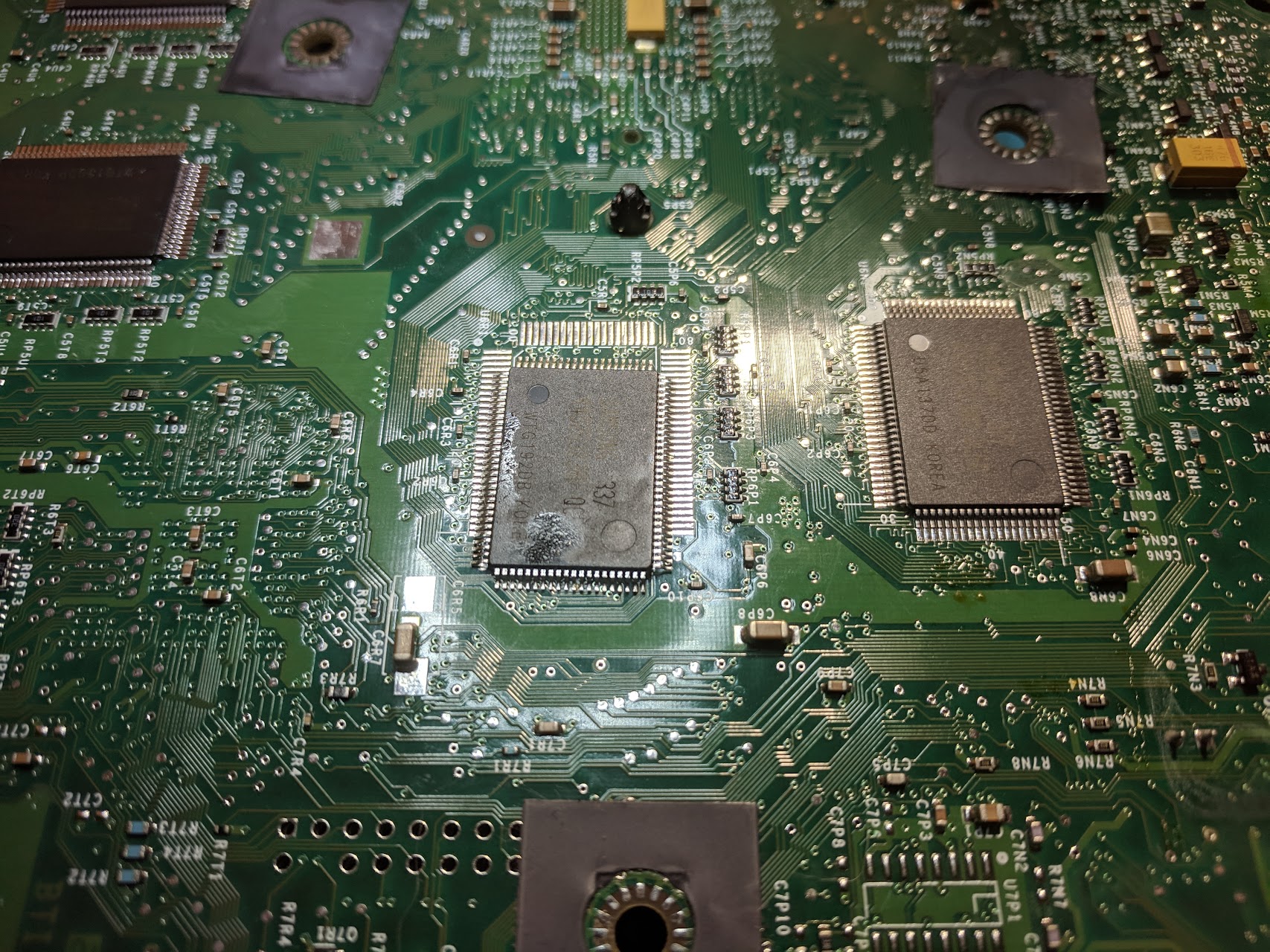
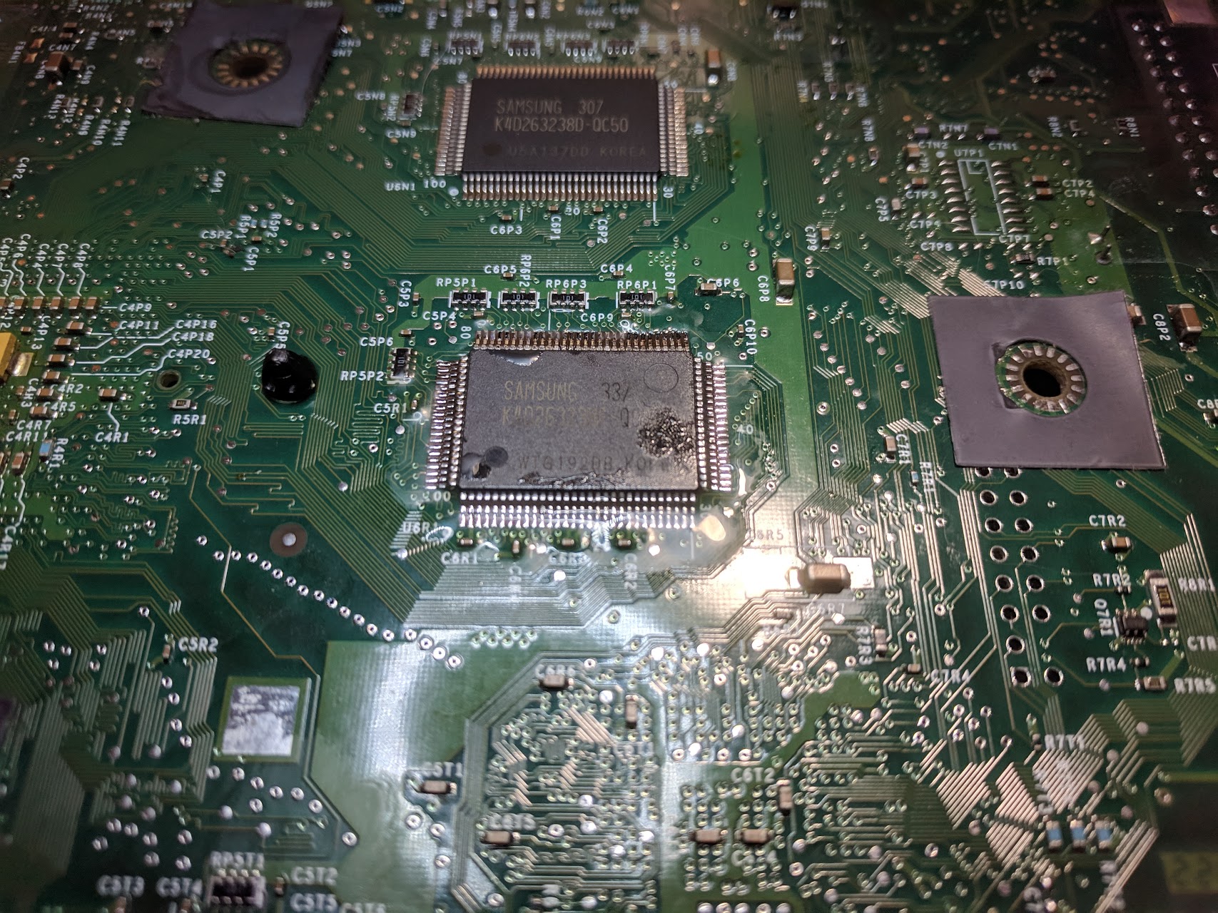
Hey, do you still have your donor motherboard? I upgraded the CPU in my rev 1.0, but when removing the plastic clips my screwdriver slipped and knocked off resistor R5N1, and the XBox is FRAGing.
This resistor is visible, but the value is not quite readable in your 4th picture of your donor board. I would be immensely appreciative if you could read the numbers marked on the resistor to me. It’s near the left edge of your image.
https://imgur.com/a/yQZOMHf
Hi, Thanks for documenting this. Used to do this regularly back in the day, selling chips and also undoldering off dead boards and soldering onto new to do the upgrades.
Back then it was soldering iron and chipquick, how much easier it would have been