SCPH-39001 PS2 Modbo 5.0 modchip installation (V7 NTSC board)
Earlier this month I installed a Modbo 4.0 modchip into my SCPH-70012 PS2 slim console. Since I also own an SCPH-39001 PS2 fat, I decided to install a modchip into it. Modchips for the PlayStation 2 you to get more out of your PS2. Things like playing games from other regions, playing PS1 and PS2 backups, and running homebrew applications. This blog post covers the installation of the Modbo 5.0 modchip into my SCPH-39001 PS2 fat console.
Update: I put together a Modbo modchip installation guide that covers all board revisions. You can find that guide here.
Things you’ll need
- An SCPH-39001 PS2 fat console
- Tools to take apart the PS2
- A Modbo 4.0 or Modbo 5.0 modchip. They are pin compatible, I bought my chip from Eurasia.
- 30 AWG kynar insulated wire wrapping wire
- A soldering iron and solder
Both the Modbo 4.0 and Modbo 5.0 modchips are good modchips. The Modbo 5.0 chip allows booting homebrew directly off of a USB flash drive, which is less important for a PS2 fat, because of the hard drive bay, but still a nice feature.
I’d also like to mention that I was able to install the modchip with a pretty standard 1.6mm chisel tip on my Hakko FX-888D soldering iron. In other words you don’t need a super special tip for your soldering iron. You just need patience, good eyes, and a steady hand.
Soldering tips
At the time of writing this post I have installed a modchip into two different PS1 systems, two different PS2 systems, and soldered a Teensy to a PS3 slim. I’ve learned a lot along the way, so I’d like to share some tips that may help your modchip installation experience be a smoother one.
Since these tips apply across a lot of posts, I’ve put them into a single page that is linked to from multiple posts.
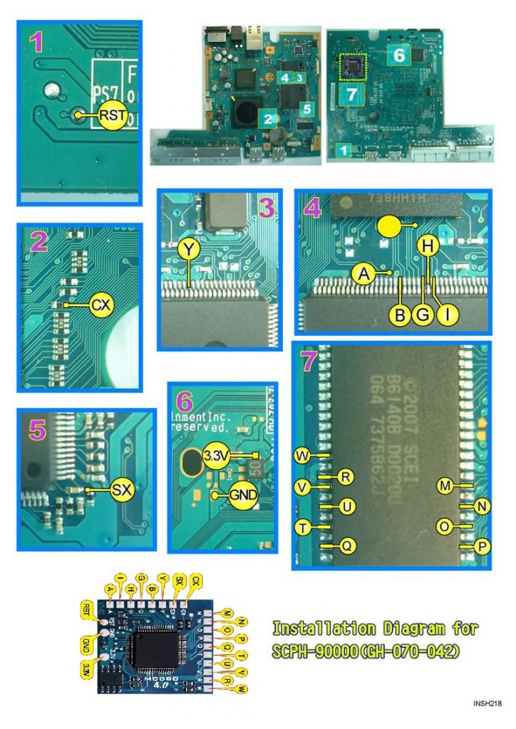
Modchip installation diagram
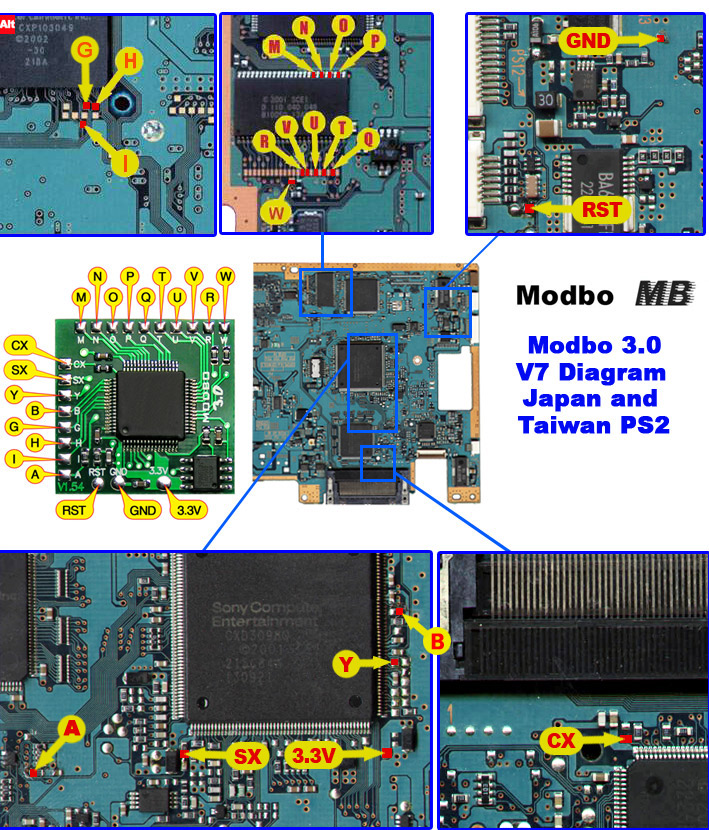
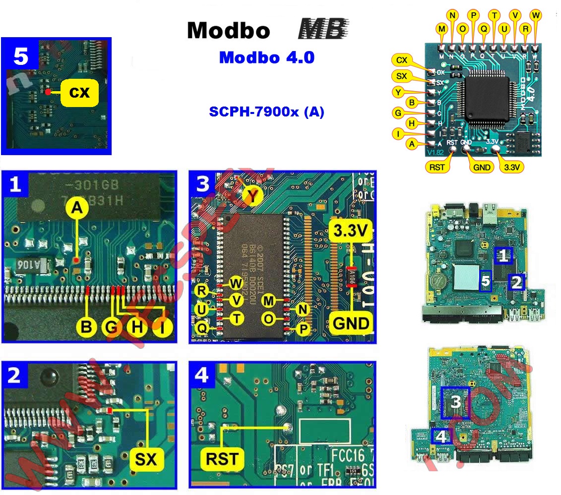
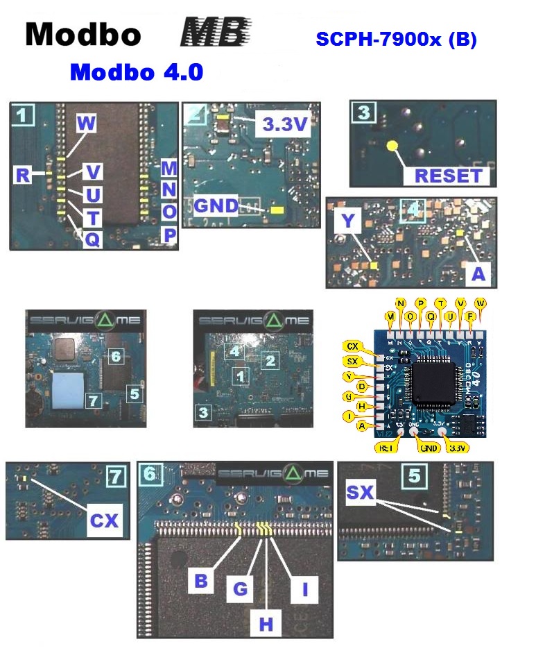
Above is an image of the installation diagram for the Modbo 3.0 diagram for NTSC V7 PS2 consoles. This diagram is the same for Modbo 4.0 and Modbo 5.0 chips. If you need a diagram for another version of the PS2 just leave a comment and I’ll upload a copy for you.
The diagram is labeled for Japanese and Taiwanese PS2 consoles, but it’s the same wiring for American consoles. I found many diagrams that didn’t include the point H, which is actually needed. Without pin H soldered I was able to run homebrew, but not run game backups from the disc drive, so pin H is important.
As you can see from the diagram there are a total of 21 wires that need to be soldered from the PS2 to the modchip. The chip comes with double sided tape that you use to stick it to the board.
I chose to mount my modchip on top of one of the larger chips in the middle of where all of the wires needed to go. I also made sure that the metal shell would fit back on with the chip in that position before I stuck it to the board. Make sure you leave room by the modchip for a few wires to run to the legs of the chip to the left.
Modchip installation
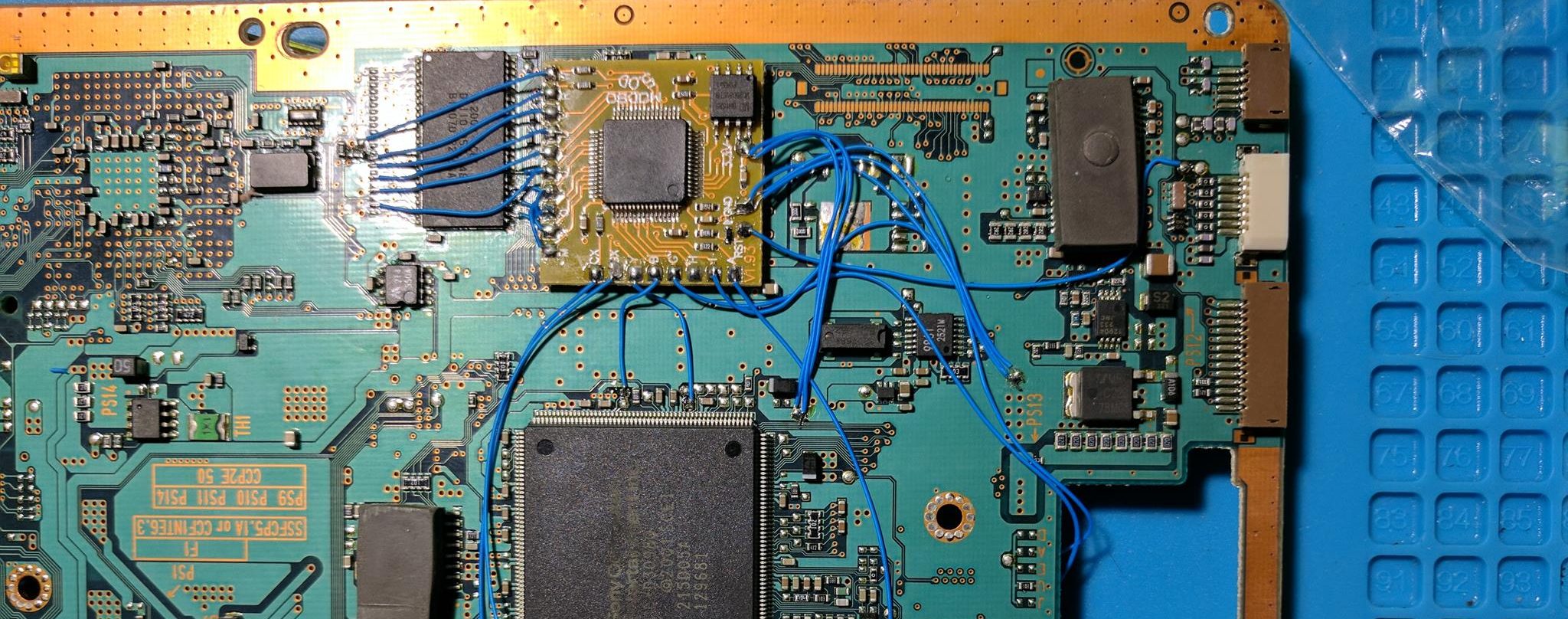
With the modchip mounted I soldered each wire to the board. I started with the pads and legs of the chip to the left of the chip, and then followed a counter clockwise pattern around the modchip once I finished soldering those first set of wires. Above is an image of what my installation looked like after I finished with the left side of the modchip.
There were a lot of places where I had to solder wires to components surrounded by a lot of other components. I’d recommend positioning the board and your soldering iron so that you can solder at a good angle.
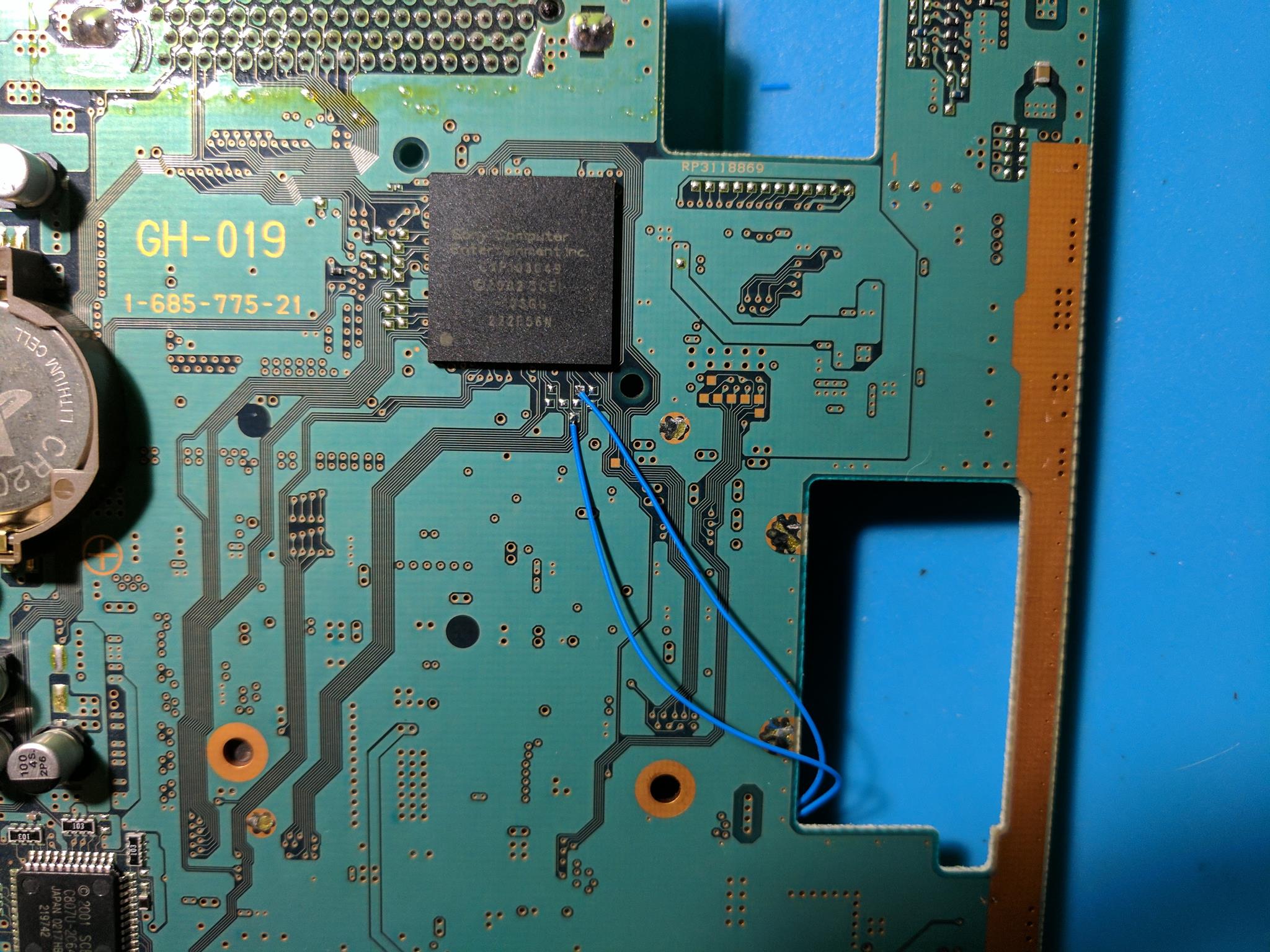
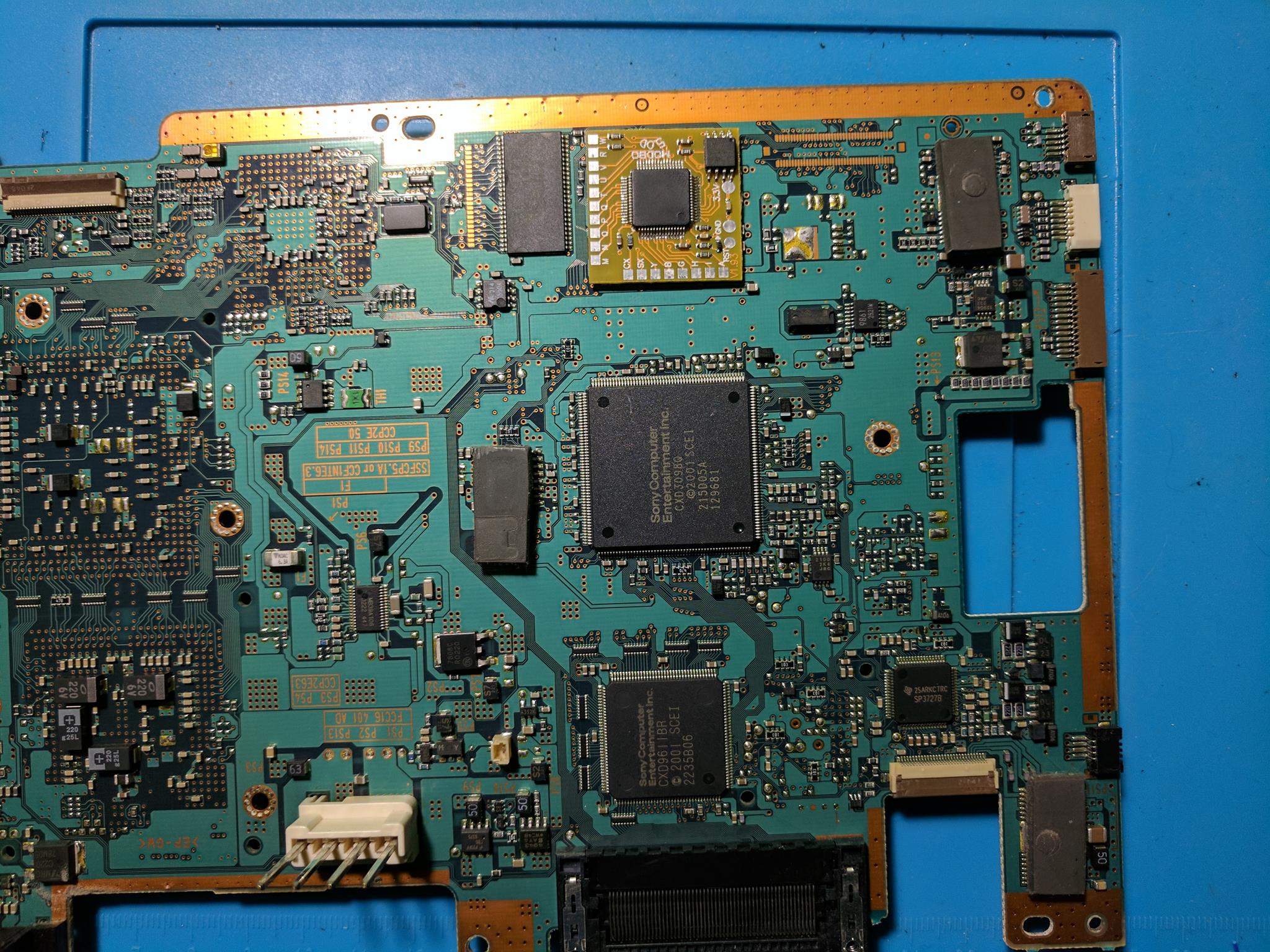
Above is an image of the back of the board. I ran the wires through the big hole, and left a little bit of extra slack so I could move them around if something got in their way when putting the console back together. This picture was taken before I figured out that I needed to solder the H wire to the modchip.
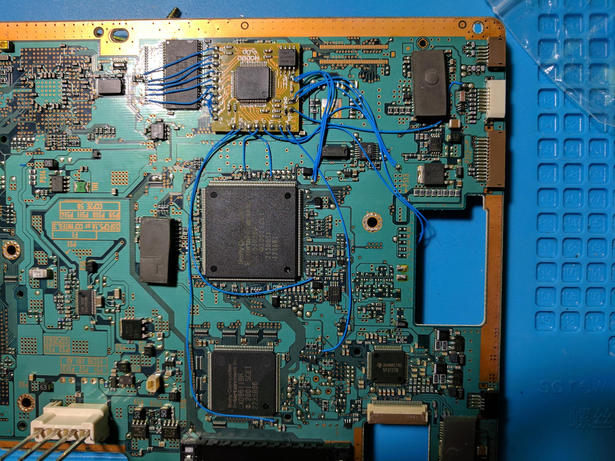
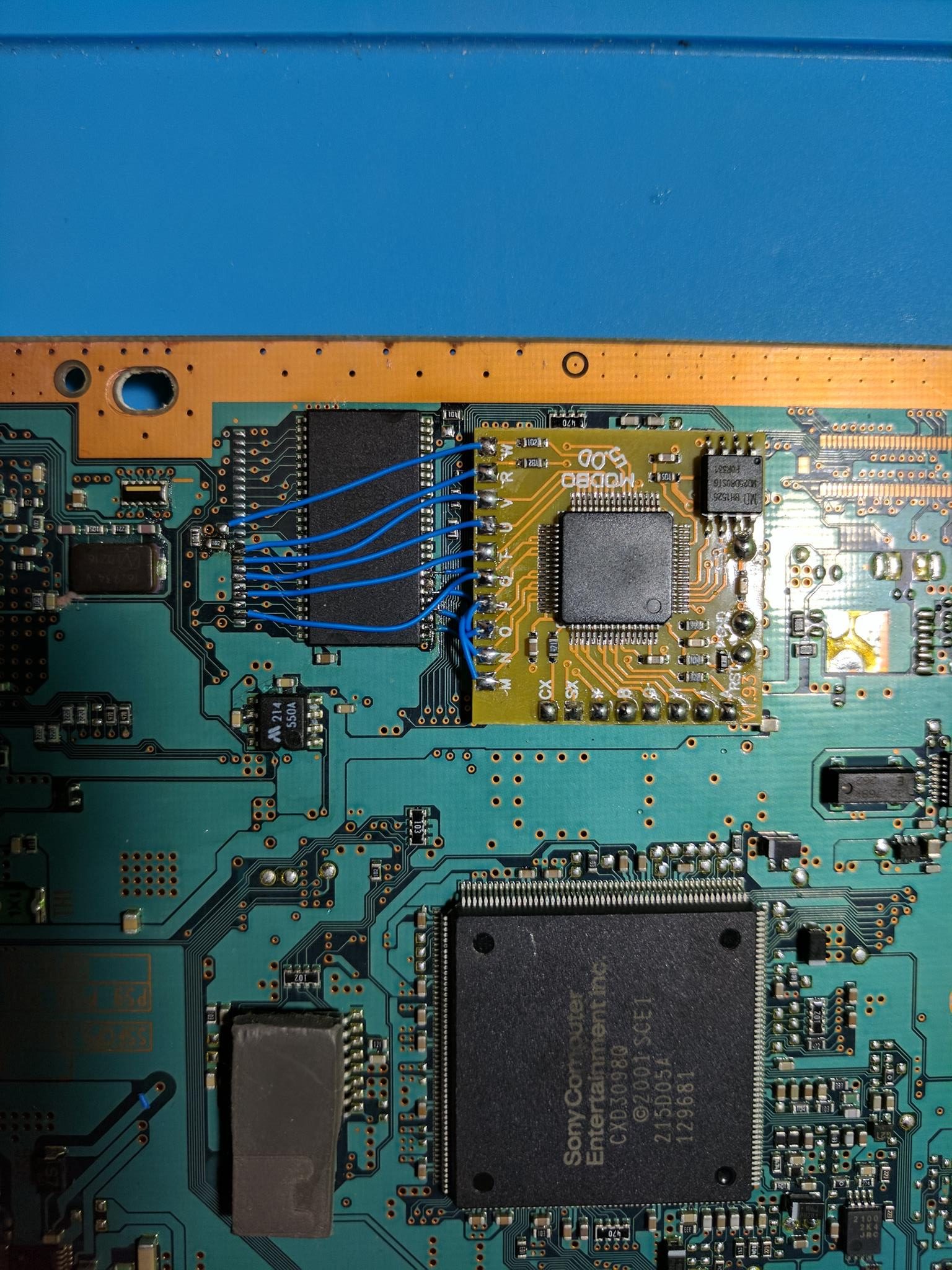
Eventually I finished soldering all of the wires to the board, and the image above is the result. As you can see I routed three wires for ground, and three wires for 3.3V. You could alternatively just use a single larger diameter wire for each power line.
Putting everything back together
Once I had soldered the modchip to the board, I could put the console back together. I started by taping over all of the points I soldered to, including most of the modchip. Taping prevents any of the connections from being shorted with the case, and also helps hold the wires in place.
I had no troubles putting the console back together like I did with my PS2 slim. Everything fit back together nicely.
Final thoughts
I was able to install my modchip in less than an hour. I found the installation process to be more difficult than the installation of a modchip on a PS1, or soldering a Teensy to a PS3 Slim, but very similar to the installation of a modchip onto my PS2 slim.
After installing the modchip I was able to read PS1 game backups, and genuine PS2 games just fine, but wasn’t able to run PS2 game backups. I was able to play PS2 game backups after I adjusted the DVD potentiometer on the laser. So if you have an old PS2 and are having some problems playing game backups it could possibly be an issue with the laser.
I want to put a 5.0 modbo in schp 39000 PAL that diagram use
I want to install a V5.0 modbo on a schp 39004 PAL board which diagram do I use?
See my modchip guide: https://quade.co/ps2-modchip-guide/modbo/
HOW DID YOU CALIBRATE THE LENS WITH THE POTENTIOMETERS, ID YOU USE SOME OHMS VALUES?
This is a good guide: http://nuangel.net/pcdownloads/PlayStation2_Laser_Repair.pdf
Hello there have you got a diagram for modbo 5 for a UK ps2 fat scph50003.
Kind regards
Mike
Here’s a link to the Modbo diagram for your V9 PAL system.
I have the exact same PS2 and it reads backups without messing with the laser pot. I used a different SX point, though. I used the point right above the one you used. From the diagram, it looks to me like you used the wrong one.
Do you know where i can find a diagram for installation of the Modbo 5.0 modchip in a V4 PS2? Any help would be greatly appreciated.
There are two versions of the v4, depending if there is a gap in the pins of the BIOS chip or not.
I am soon going to take apart my SCPH-39001 model, and know that i unfortunately will not be able to know if it is a V7 or V8 motherboard till i read the number off of it. If it ends up being V8, is there anyway that i can have the V8 NTSC motherboard wiring diagram as well. I appreciate any help received!
V7 and V8 both use the same diagram.

Hello there have you got a diagram for modbo 5 for ps2 fat scph50004 PAL? I appreciate any help received!
The 50004 is either a V9 or a V10. I attached the diagrams for both. V9 and V10 also need to have a laser fix installed which is covered in this video: https://www.youtube.com/watch?v=WAfETZeW70M
hi i have scph 90002 cb i couldn find any diagram for my one.since you have helped lot pls help me
A SCPH-90002 is either a V17 or V18. Here are the diagrams I have for those models.
V17:
V18:
For 39008 it will be the same?
Yes, as long as the board revision is the same (you’ll be able to see if things match up when you take apart your system). Let me know if it doesn’t match and I can upload diagrams.
Hello
I have a SCPH 30003r (PAL) B3168713 which diagram do I need for Modbo 5.0? I thought v3 diagram but probably wrong, be my luck its probably the hardest! :-} what type of wire and awg size would you recommend?
Thanks
Pete
Sorry for the delay in getting back to you, but the SCPH-30003R is likely either a V5 or a V6 board (both use the same diagrams). 30 AWG wire works well, but use thicker wire for the 5V and GND connections (something like 22 AWG or 24 AWG).
Diagrams:
https://quade.co/ps2-modchip-guide/modbo/v5/
https://quade.co/ps2-modchip-guide/modbo/v6/
Is thier any diagram for 39001 v7 modbo4.0
https://quade.co/ps2-modchip-guide/modbo/v7/
hello i have a different chip M-2 P320-L8 i cant find the Modchip installation diagram i have a SCPH-39001 can you help with a diagram
Could you post a link to a picture of the chip?
https://imgur.com/gallery/BinjCPy
This diagram should work: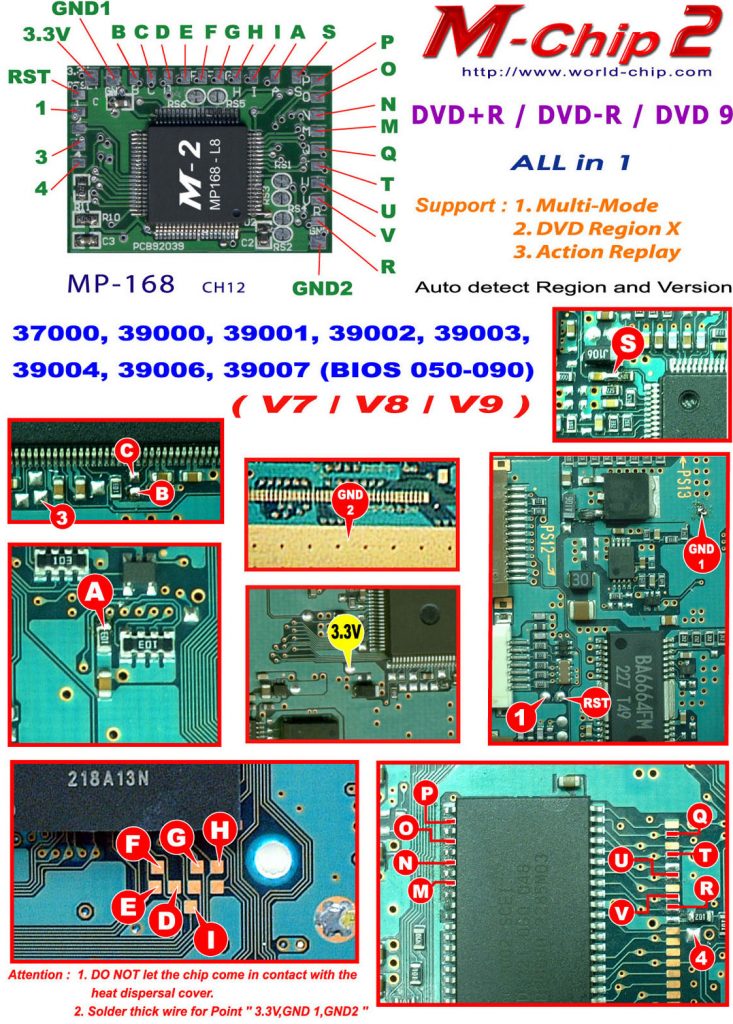
Thank you
sorry for the hassle but can you point out where are points C,B, and 3 on the board i have located all other points sorry for the inconvenience i am new to this
They are near where Y and B are in this Modbo diagram.
Witam mam chipmodo 5.0 i potrzebuje schemat to modelu ps2 SCPH-93003
Z GÓRY DZIĘKUJĘ I POZDRAWIAM
After mod chip install can i play games via usb,hdd and dvd ?
Yes.
Need installation guide for modbo 5.0
Schp-70004 v12
https://quade.co/ps2-modchip-guide/modbo/
I just ordered a Modbo from you on eBay and I’m gonna put it in a 39001 once I get it, but I was wondering if you had any wiring diagrams for a *ancient* NEO4 that I would like to try in a old 30001 v4 that I have. I’ve only found one pic online (that looks like a v4) but some of the wires are not really identifiable as to where they go: http://www.logic-sunrise.com/images/techs/34796/1-mod-xkey-jtag-rgh-flash-xbox-360-walentek-3.jpg
I don’t have any diagrams for the NEO4 chips.
Ok, thanks. I thought that it would be worth a shot asking.
I would like to have the wiring diagrams for a MOBO 5.0 v1.93 which will be installed onto a SCPH 39001 GH-019 motherboard if you could please send them to me
thanks
That’s what this page is.
ok just dont want to destroy my system its also a usa version
Hi would it hurt if I was to just add the H connection even if its not needed? Would rather not want to dismantle everything to just remove 1 wire. As its hard to determine weather you have an early or late model v7 board setup. Thanks
Yeah, no downside in having H.
Sir good pm
I want to modify my ps2 phat gh-015
Using hdd can you give me a guide modbo 5.0 is my modchip what letters is not belong to connect to the board?
hello … I went to solder the M-N-O-P wires. however, I ended up soldering the points of the bios itself. can you help me ???
You are supposed to solder to the BIOS itself for those pins.
Hello, I have the SCPH30004 console, could you please post here under my comment which one diagram should I use, many thanks in advance.
See https://quade.co/mbo