V5 Modbo modchip installation diagram
One of the revisions of the fat PlayStation 2 was the V5. They were found in many of the SCPH-3000x systems. Matching console model numbers and board numbers are listed below. V6 consoles also have the same model numbers, board revisions numbers, and installation diagrams.
You can find the model number on the sticker on the bottom of the console, and the board number is printed on the PS2 main board if you take apart your console. Note that there can be multiple board numbers within a specific model number.
- NTSC-J (Japan):
- SCPH-30000R (GH-015)
- SCPH-30005R (GH-015)
- SCPH-30006R (GH-015)
- SCPH-30007R (GH-015)
- NTSC-U/C (United States)
- SCPH-30001R (GH-015)
- PAL
- SCPH-30002R (GH-015)
- SCPH-30003R (GH-015)
- SCPH-30004R (GH-015)
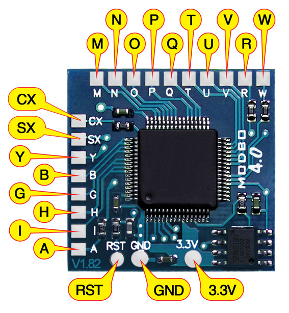
Note that there are multiple versions of the Modbo modchips available, but the installation diagrams are all the same. Some example versions are Modbo 3.0, Modbo 4.0, Modbo 5.0, and Modbo 750.
For more information about Modbo modchips click here, for more information about PS2 modchips in general click here.
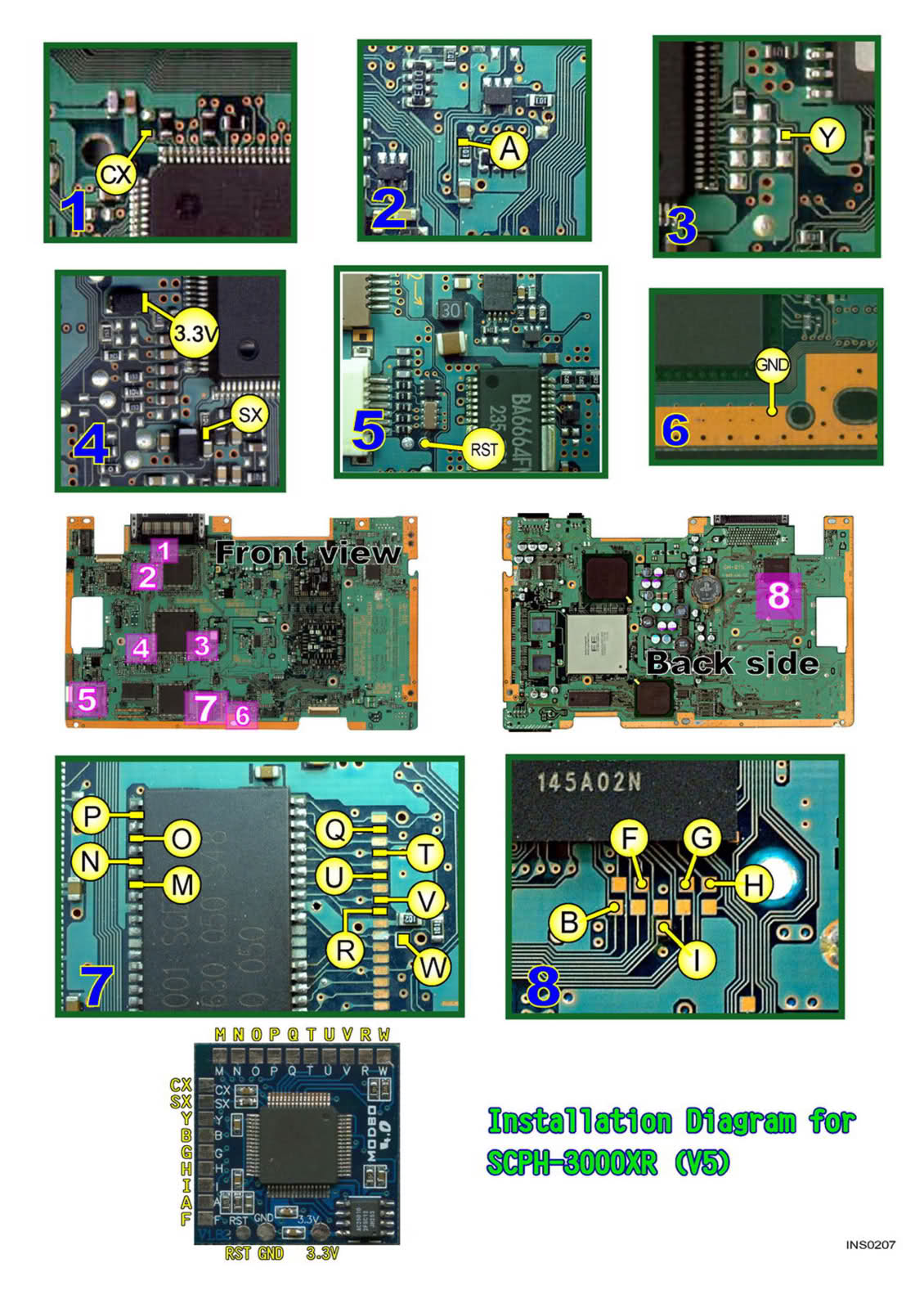
V5 Modbo installation diagram
Installation tips
Here are some tips I have for you when you are soldering your chip into a V5.
- Using 30 AWG solid core wire works well for most of the points.
- Use some thicker wire for the 5V and ground wires.
Example installations
This section has photos of some successful installations which you can use to get a better understanding of how everything is wired and positioned. Leave a comment and I’ll add your installation to the list
- Nobody yet.
Hi, I’ve successfully modded a v5 GH-15 this time, here are the pictures : https://t.co/edTjBAjNdG
Hi, GH-015 successfully modded on 20/6/20.
Thank you for the useful guide, I got my chip working. Maybe not the best place for the chip since it make it a bit tall.
Hi, quick question. Does A go on the capacitor?
Yes, but the small black part is a resistor and not a capacitor.
Above the resistor or on the pcb? First time I’ve been soldering wires to surface resistors.
The resistor is connected to pads on the PCB. So both.
On the Modbo version 5.0 there is no “F” pad so what are you supposed to do there?
Just ignore the F pin in the diagram.
Thanks, and I got it working 🙂
If I were to have an SCPH-30001 and an SCPH-30006 models on hand, being that some parts on each were broken could I combine the remaining working parts to make a working ps2?
Yes you can combine consoles (assuming they are the same version, or at least have the same connections).
Hi , for these old models you have to make the Romeo MOD or Matrix Fix with PIC so as not burn the lens ? or not need ?
Thanks
No.
The PS1 games are not rétrocompatible ? 🙁
What do you mean?
I can’t read burned PS1 games, is that normal?
You should be able to read burned PS1 games. The SX pin is used for PS1 games.
The pin SX it’s ok but not boot . 🙁
setting lens ? picture disque PlayStation 2 blue …
Thanks for the great information and guides. I’ve seen many conflicting references to the requirement (or not) for point “H” on the Modbo chip. Is it correct that point “H” only needs to be connected for NTSC boards and not PAL boards?
I am almost certain that the H pin is always needed regardless of region. I’m not in a PAL country so I haven’t installed into many PAL systems, but when I do I have always found the H wire to be necessary. Comments from other people seem to also go along with this. I did not make these old diagrams, so I don’t know where the not needing H for PAL systems came from. Maybe it wasn’t needed on the original Matrix Infinity chips, but over the years things changed and the current firmware and hardware on the Chinese clone… Read more »
Successfully worked on GH-15 motherboard.
The pad on the V point was lifted by accident. I managed to fix it by soldering the wire to the tiny circle on the left. Scratched it a bit first and it worked. Be very careful with the bios points and don’t press more than 1 second otherwise the pads will lift!