SNES Jr. (SNS-101) RGB SCART video output using THS7374 amp
I recently bought an Open Source Scan Converter, or OSSC, primarily to make PlayStation 1 games look better on my display. After seeing how well RGB looked on the PS1, I had to try it on other consoles.
I ended up buying an SNES Jr. (SNS-101) for the improved visual quality from the 1-CHIP board design. The biggest downside of the original SNES Mini is that it doesn’t output RGB SCART out of the box, so I installed an THS7374 based amplifier, which is what this guide covers.
What is RGB video?
In the United States most older video game consoles used either RF or composite video (coaxial cable like what you get cable TV out of, or the yellow/red/white cables) to output video onto a TV. These video output options are passable on a CRT television, but on a digital HDTV it can look quite bad.
Both RF and composite video is sent through a single cable (RF also sends audio over the same wire, while composite separates audio into two more wires). When all of the visual information is put into a single wire it can look fuzzy and dull, lacking the well defined edges and colors that you’d see with something like an emulator.
RGB improves video quality by using three separate wires for video, one for red, one for green, and one for blue. Each color gets its own wire, and each audio channel gets its own wire. With RGB video your console can output super clean video to your TV.
Why don’t people use RGB video?
In the United States RGB video was never available on regular televisions, so it was never an option. In Europe and Japan it was a common connector found on televisions. Europeans used the SCART connector, and the Japanese used the JP-21 connector.
Because televisions in the United States don’t have RGB video inputs, you will need to use a converter. There are cheap SCART to HDMI converters, as well as more expensive converters like the OSSC and Framemeister.
How do I get RGB video out of a Super Nintendo?
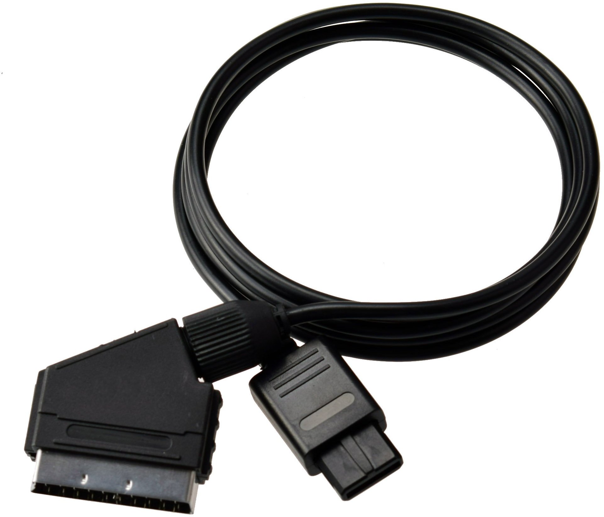
Most consoles were designed to be easily adaptable to a global market, so most consoles have the ability to output RGB video. In the case of the SNES all original design (fat) versions of the console can output RGB video directly from the Nintendo Multi AV output port, no modding needed. Just use a converter, and a cable like this one.
The problem with early SNES systems is that they use two video chips, which don’t always have the clearest image, even when using RGB. A small number of original SNES systems released towards the end of the system’s life use an improved 1-CHIP design that has much improved visual clarity.
An original fat 1-CHIP system can output RGB directly, but they can be hard to track down. It’s easier to find a SNES Jr. (SNS-101) and use that since they all use the 1-CHIP design.
The problem with the SNES Jr. is that Nintendo removed the native RGB video output support, so you’ll need to mod the system using a guide like this one.
SNES Jr. RGB video output mod options
There are several ways to add RGB video back to the SNES Jr.
- Using the built in SNES Jr. RGB amplifier
- This is the cheapest option, since it only requires that you have wire and a few resistors.
- It’s also the hardest to install since you’ll need to solder wires directly to a chip, through a hole in the board, to the video output port.
- Video quality is very good.
- Using a THS7314 based amplifier
- This costs more money than using the built in amplifier.
- It is easier to install.
- Video quality isn’t quite as good as the built in RGB amplifier, or the THS7374.
- Using a THS7374 based amplifier
- This is the most expensive option.
- The installation process is the same as with the THS7314 board.
- Video quality is very good.
This post covers just the THS7374 based amplifier mod, but if you’d like to learn more about the other mods then you can check out this website.
A look at my THS7374 amplifier board

Instead of buying prebuilt THS7374 based amplifier boards for about $30.00, I made my own boards for much less. The goal is to begin to sell these on my eBay store if there is enough interest.
Instead of starting from scratch I found an existing design on GitHub. In particular I went with the SNES_RGBAmp_wCSYNC version. I may eventually design my own board, but for now this works perfectly and is pretty flexible.
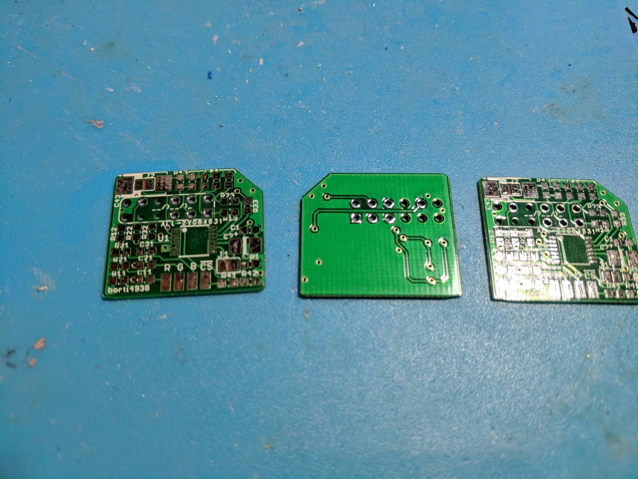
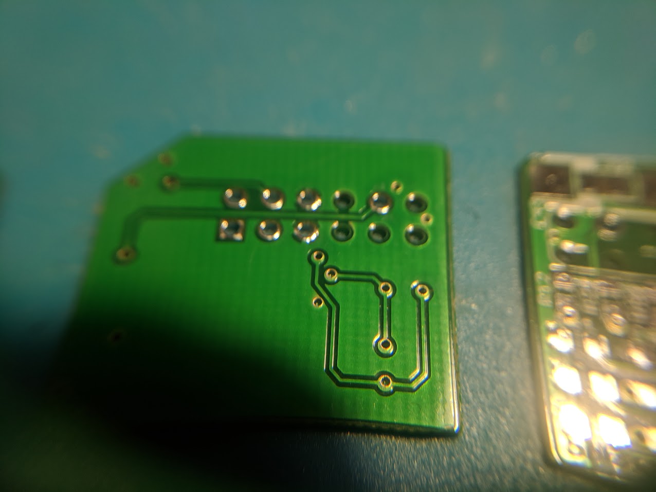
I had my boards made at a Chinese company called AllPCB. They were able to get five boards made and sent to my house within a week for just $12.00. The PCB’s turned out very well. I chose 0.6mm thickness so that the boards would more easily fit underneath the console’s motherboards.
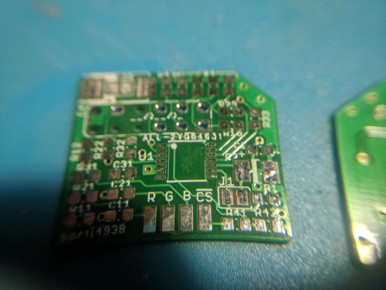
Once the boards arrived I soldered all of the necessary components to them using a cheap hot air rework station, and solder paste. I ended up making three of the boards so I could mod my SNES, N64, and then have an extra left over.
The end result is good. I applied a little too much solder paste to some of the pads, but nothing ended up bridging. It can be hard to get the right amount of paste out of the syringe.

I ended up selling the third board on eBay and plan on making another larger batch in the near future. I’ll update this post with more information once they’re available.
THS7374 amplifier board installation into an SNES Jr.
As I said earlier, THS7374 based amplifiers are very easy to install into an SNES Jr. It only requires soldering four wires to the console and the amplifier.
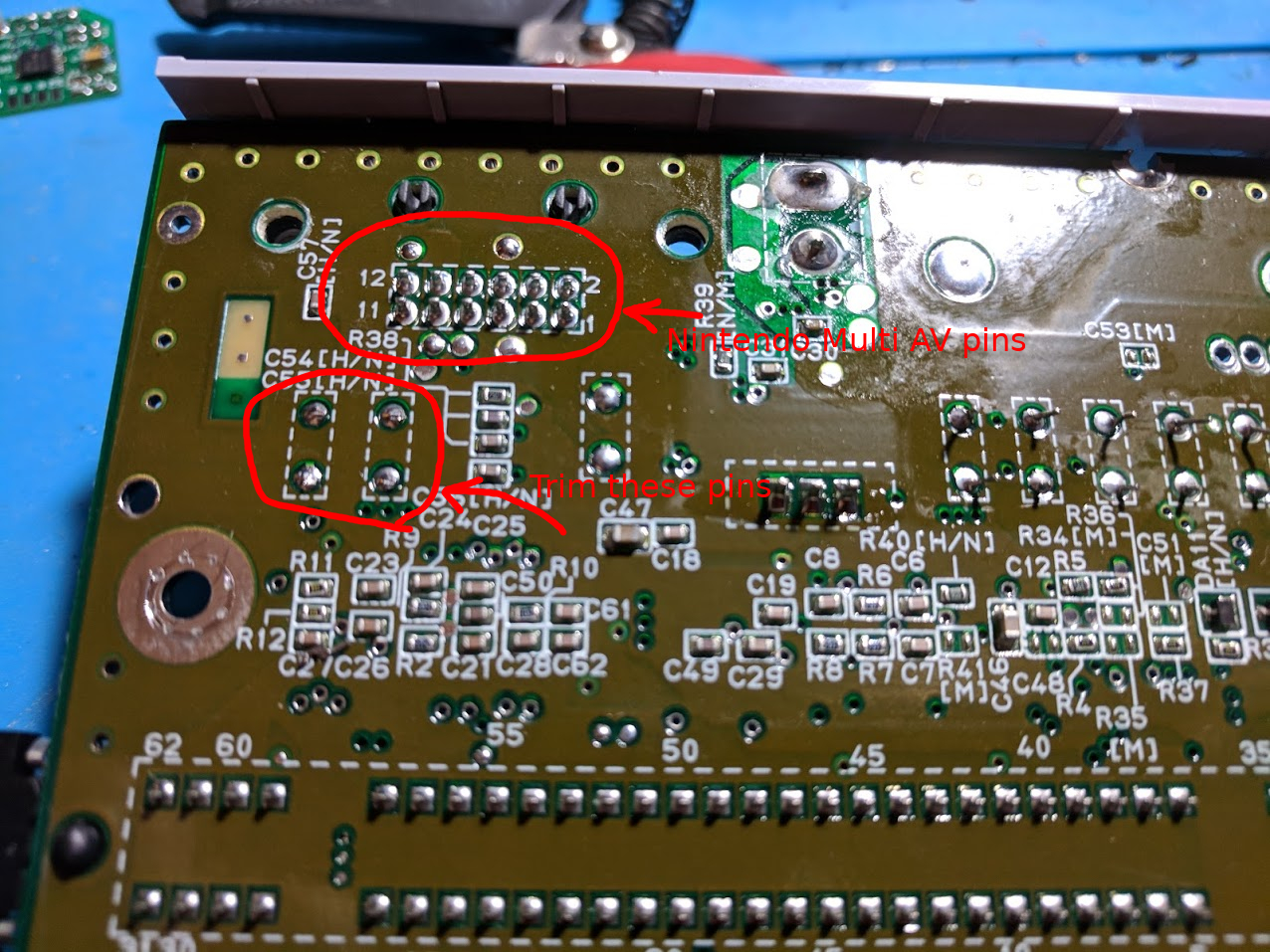
Begin by locating the 12-pin Nintendo AV connector’s pins on the bottom of the SNES board. You’ll need to trim the ends of the pins labeled in the picture above. Use something like side cutters. This is needed so that the amplifier board can sit more flush with the console’s board.
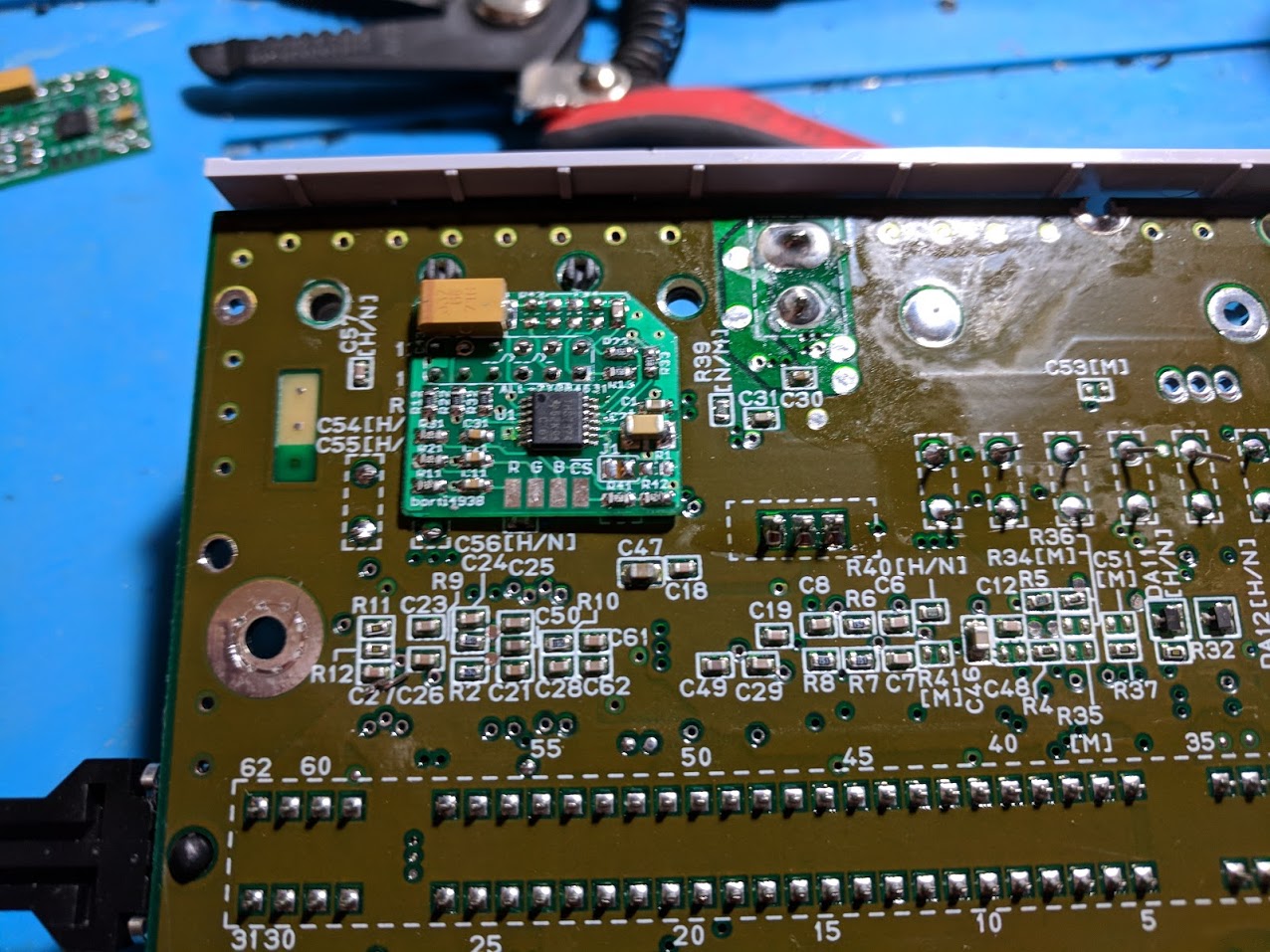
With those pins trimmed, you can place the THS7374 amplifier board the AV pins like the picture above. I put some tape underneath the board just to prevent any possible contact with anything underneath.
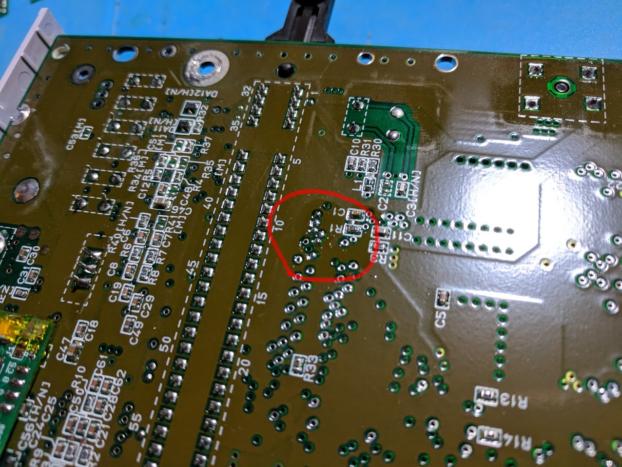
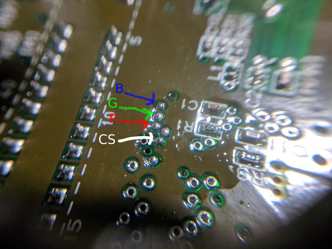
Next locate the R, G, B, and CS vias on your board. The picture above shows where the pins are located, and below is a close up picture of them with pin labels. You’ll want to tin the vias using flux and solder. A concave shaped soldering iron tip is really useful for this.
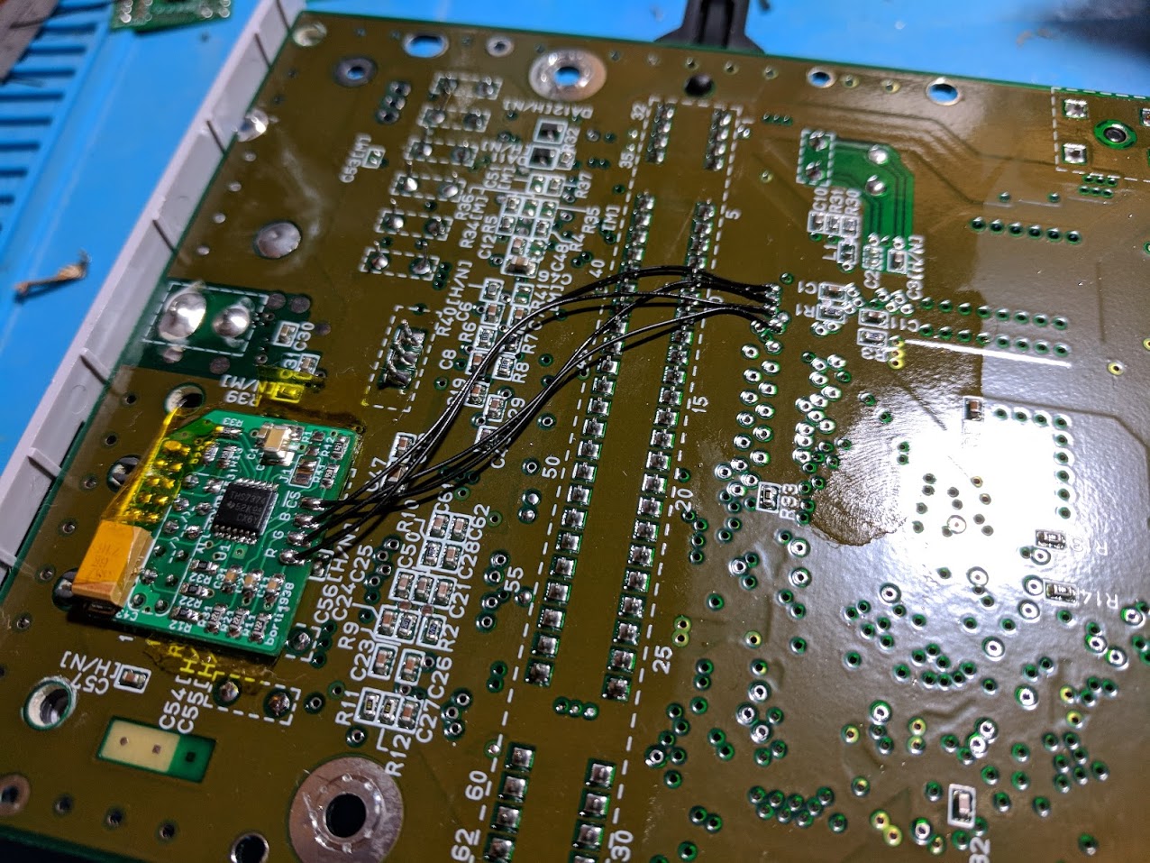
Now you just need to connect everything. First solder the amplifier board to the AV pins, you’ll only need to solder the pins that have the annular ring around them. Then solder a short wire between each of the four pins. I used 30 AWG wire.
When you’re done it should look something like the picture above. Once you’ve finished soldering you can put your console back together.
Mod results
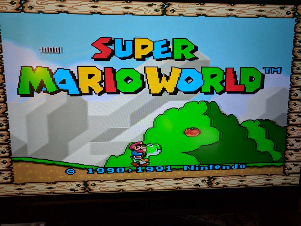
The video quality coming out of my SNES Jr. with the THS7374 amplifier installed is very good, a significant improvement over the composite video it came with. Above is a picture I took with my phone of the title screen of Super Mario World through the OSSC.
I find the video quality of RGB with the SNES Jr. to be similar to what you’d get using a good SNES emulator. Since I prefer playing games on original hardware this is exactly what I was looking for.
quick question, are the pins 5&6 on the SNES where the RGB board mount, are those both ground, my multi meter on these pins gives me continuity beep so thought will double check , thanks
No, it mounds so all of the pins are aligned with the holes in the amp board. https://gamesx.com/wiki/doku.php?id=av:nintendomultiav
thanks so, both are ground pins. Cheers
[…] ← Previous […]