Four switch Atari 2600 RGB mod installation guide (2600RGB)
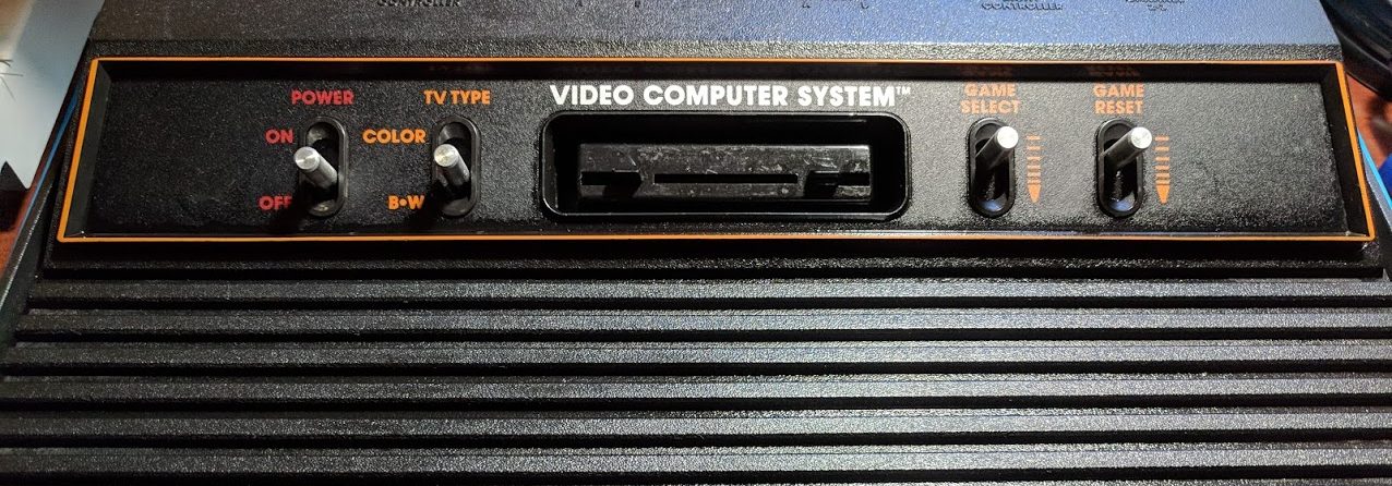
It has been a while since my last post and I have a lot of projects I have completed since then that I haven’t written about. I plan on working backwards starting with the most recent mod I did. This post covers how to install the 2600RGB board into a four switch Atari 2600, which allows the Atari 2600 console to output RGB video, a huge improvement over the native RF video output.
What is RGB video?
In the United States most older video game consoles used either RF or composite video (coaxial cable like what you get cable TV out of, or the yellow/red/white cables) to output onto a TV. These video output options are passable on a CRT television, but on a digital HDTV it can look quite bad.
Both RF and composite video send video over a single cable (RF also send audio over that same wire, while composite has audio separated into two additional wires). When all of the visual information is put into a single wire it can look fuzzy and dull, lacking the well defined edges and colors that you’d see with something like an emulator, or an HDMI signal on a modern console.
RGB improves video quality by using three separate wires for video, one for red, one for green, and one for blue. Each color gets its own wire, and each audio channel gets its own wire. With RGB video your console can output super clean video to your TV.
Why don’t people use RGB video?
In the United States RGB video was never available on regular televisions, so it was never really an option. In Europe and Japan it was a common connector found on televisions. Europeans used the SCART connector, and the Japanese used the JP-21 connector.
Because televisions in the United States don’t have RGB video inputs, you will need to use a converter. There are cheap SCART to HDMI converters, as well as more expensive converters like the OSSC and Framemeister.
How do I get RGB video out of an Atari 2600?
Most consoles were designed to be easily adaptable to a global market, so most consoles have the ability to output RGB video. In the case of the Atari 2600 this isn’t the case. The RGB SCART connector didn’t even exist until 1977, the same year the Atari 2600 was released.
The Atari 2600 can only output one type of video signal out of the box, RF. In 1977 this made a lot of sense. At the time televisions were designed to have RF as the only type of input, which allowed them to be connected to over the air broadcast television antennas. The RF input was also used to connect things like VCRs and video game consoles using RF modulators.
Because the older design of the Atari 2600 additional hardware is needed to get an RGB video signal. At the time of me writing this post I only know of one Atari 2600 RGB upgrade board, it is called the 2600RGB. This post covers the installation of the 2600RGB into a four switch Atari 2600.
I’d like to mention that this guide is based on the official 2600RGB documentation.
A look at the 2600RGB Atari 2600 RGB upgrade kit
The 2600RGB kit can be purchased for $70 AUD from either a US distributor, or an Australian/International distributor. It costs a little more if you have a six switch Atari 2600, or one of the later four switch Atari 2600 Jr. systems. So it isn’t the cheapest kit, but it isn’t too bad since it comes with everything you need.
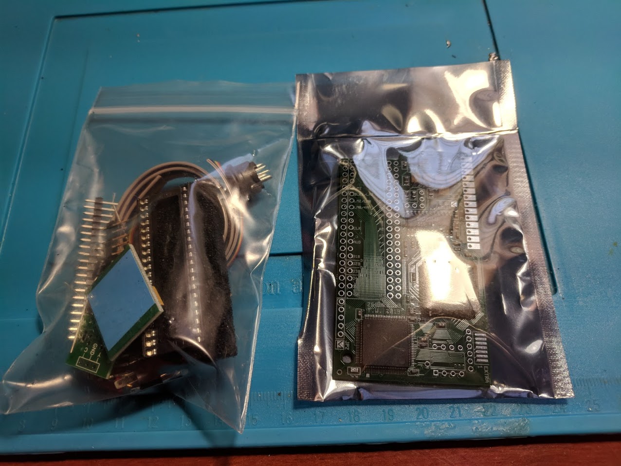
The 2600RGB kit came in two bags, one for the 2600RGB PCB, and another for everything else (capacitors, sockets, connectors, wire, voltage regulator, and some other pieces).
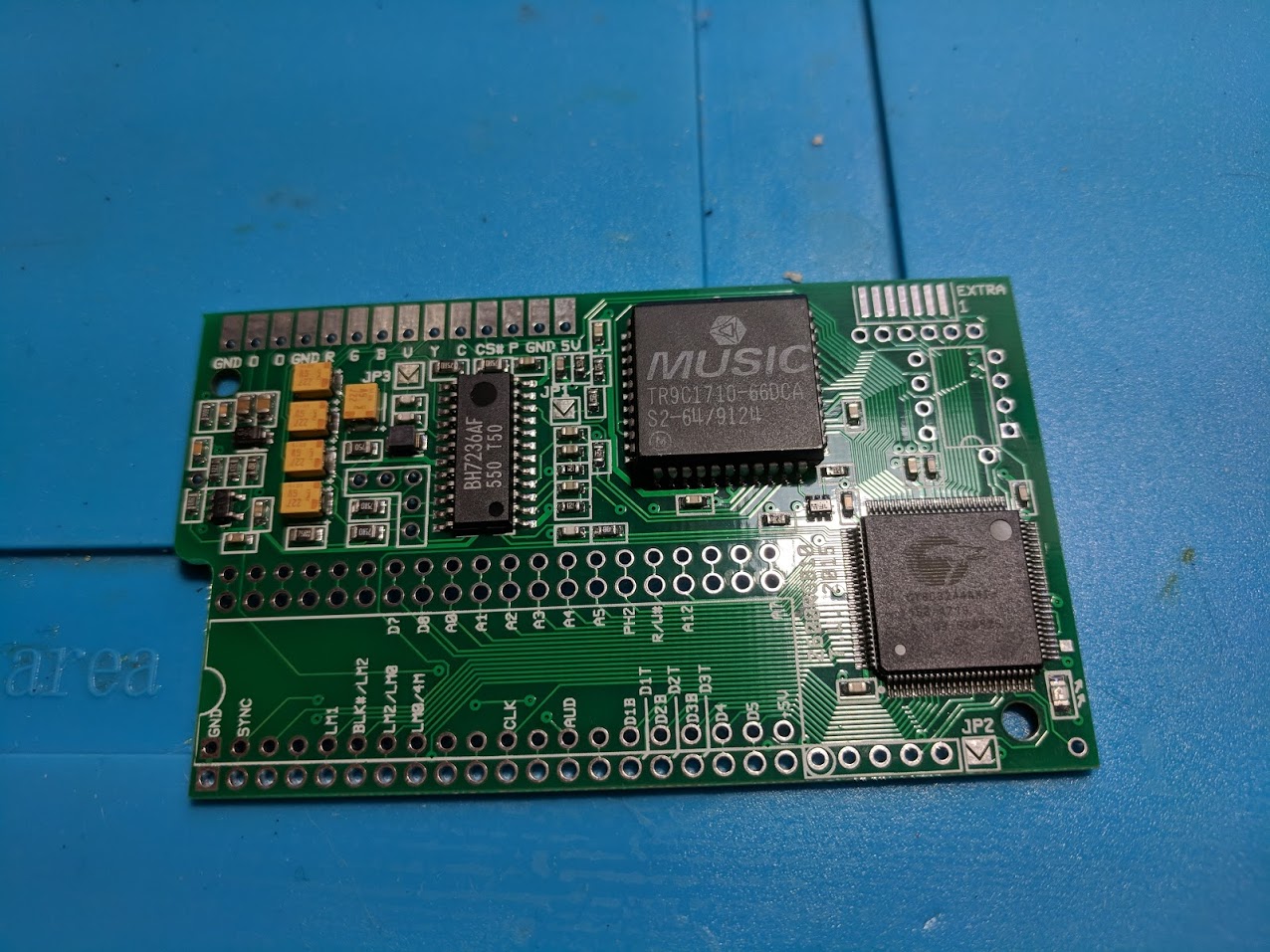
The PCB is designed to sit in between the Atari 2600’s graphics chip and the Atari 2600 main board. It plugs into the graphics chip’s socket, and the graphics chip plugs into it. There are pads for connecting composite, RGB, and S-Video video outputs, as well as connections for buttons and switches used to change modes of operations. This allows you to do things like change color palettes.
Atari 2600 RGB kit included parts
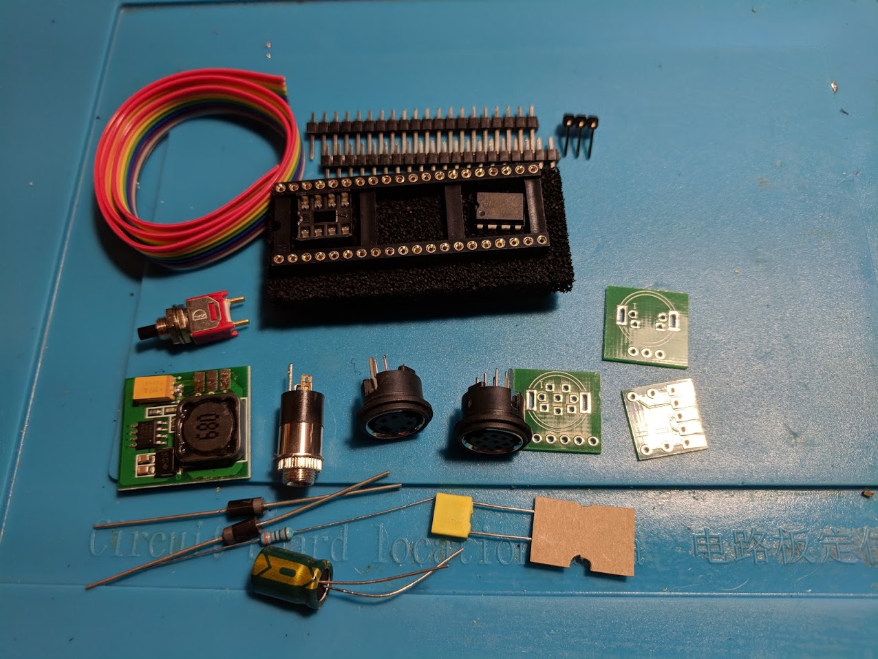
As I mentioned earlier the 2600RGB kit comes with pretty much all of the parts you need (except for things you probably already have, like wire). Here’s a list of what’s included:
- 7-pin ribbon wire (for connecting PCB to controller port buttons, and reset/game select switches).
- 2x 20-pin straight headers (for connecting the PCB to the Atari 2600’s PCB)
- 30-pin right angle header (for connecting the voltage regulator to the Atari 2600’s PCB)
- Panel mount momentary push button (for the color palette select button)
- 40-pin machine socket (for graphics chip)
- 40-pin socket (in case your Atari doesn’t already have the graphics chip in a socket)
- 8-pin socket (for the video palette EEPROM chip)
- 8-pin EEPROM chip (to store video palette information)
- Switching voltage regulator (to replace the old linear regulator inside the Atari)
- 3.5mm panel mount headphone jack (for audio output)
- Panel mount S-Video socket (to output S-Video)
- Panel mount 8-pin mini-DIN socket (to output RGB)
- PCB breakouts for S-Video and 8-pin mini-DIN sockets
- Controller mod PCB (for adding new switches to controller)
- 2x diodes (for controller PCB)
- 1x ceramic capacitor (not used)
- Ab electrolytic capacitor (for switching voltage regulator)
- 1x resistor (not used)
You’ll also need a few things that aren’t included (but you probably already have):
- A step drill bit for drilling holes into the Atari 2600 (I believe I used 3mm, 6mm, and 12mm).
- A soldering iron and solder
- Wire
- An 8-pin mini-DIN to RGB SCART cable
- A 3.5mm audio cable
- Solder sucker, or desoldering gun (if your Atari 2600’s graphics chip is soldered directly to the console’s PCB).
- Epoxy (to secure the sockets into the back of the console)
- Panel mount RCA socket (if you want to also break out the composite video signal this mod supports).
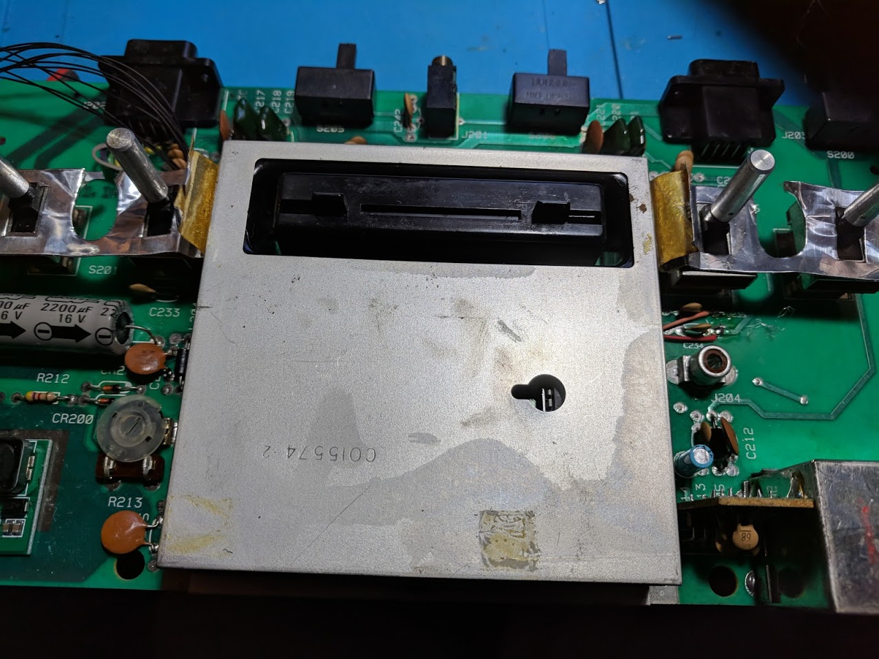
Preparing the Atari 2600 motherboard
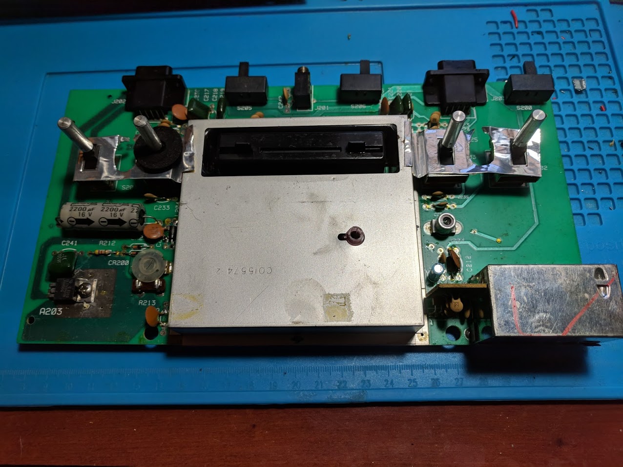
First you’ll need to remove the metal shield from the top and bottom of the console. There are several twisted metal tabs you’ll need to untwist from the top, then the shields can come off.
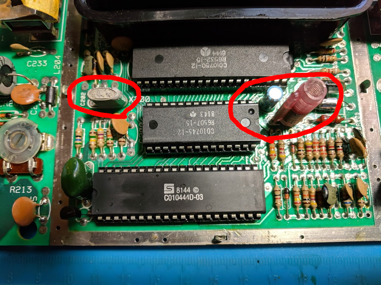
Once the shield is removed you’ll probably need to reposition some of the components over the board. Place the 2600RGB PCB on top of the lowest chip on the Atari and take note of any components in its way. In my case there was a crystal oscillator on the left, and a capacitor and inductor on the right.

Remove those components and then reattach them so they lay more flat. I attached some wire to the pins of the components so that there was more room to solder them to the board. You can also remove that bottom most chip from the PCB since we’ll be attaching it to the 2600PCB board, take note of its original orientation. Some Atari 2600’s don’t have this chip in a socket, so you may need to desolder the chip and put in the socket that came with the kit.
Preparing the 2600RGB board
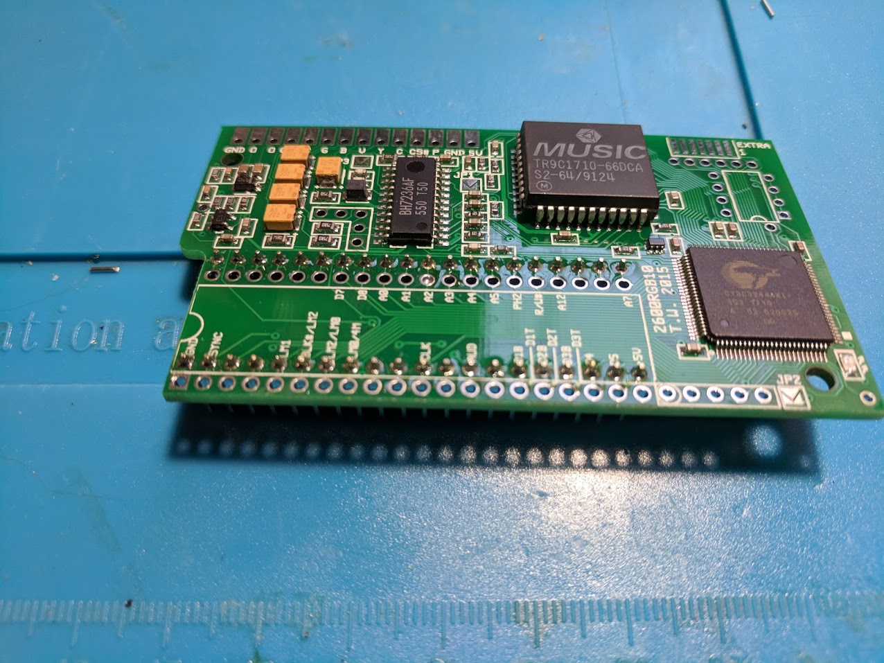
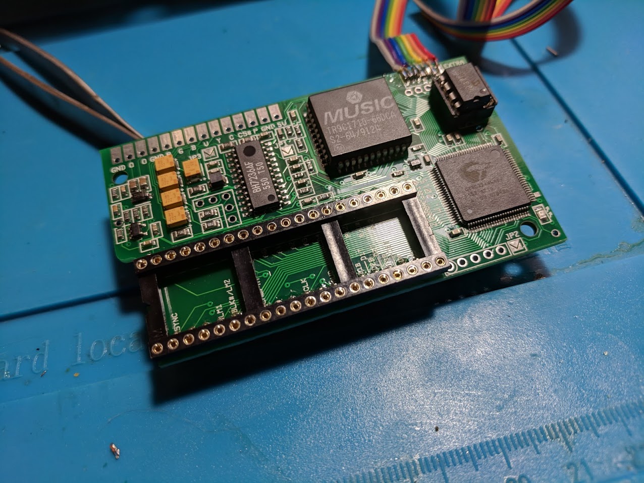
Now you’ll need to prepare the 2600RGB PCB so that it’s ready to put into the empty socket on the Atari 2600’s PCB. Begin by soldering the two 20-pin headers to the inner rows of vias on the 2600RGB. Make sure the headers are straight.
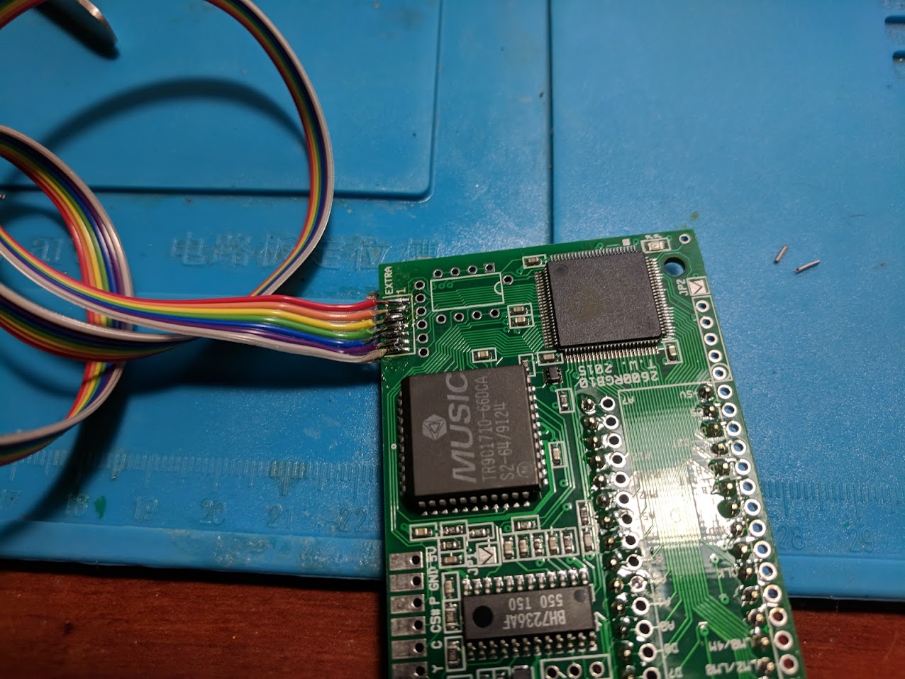
Next solder the seven pin ribbon cable to the pads labeled extra on the PCB. My soldering is a little messy since I don’t have automatic wire strippers that can strip all of the pins at once. You’ll want to tin each pad and wire with solder.

Next solder the 8-pin socket to the matching holes right next to the extra header. Take note of the orientation indicator on the PCB. Once soldered you can put the 8-pin EEPROM chip into the socket.
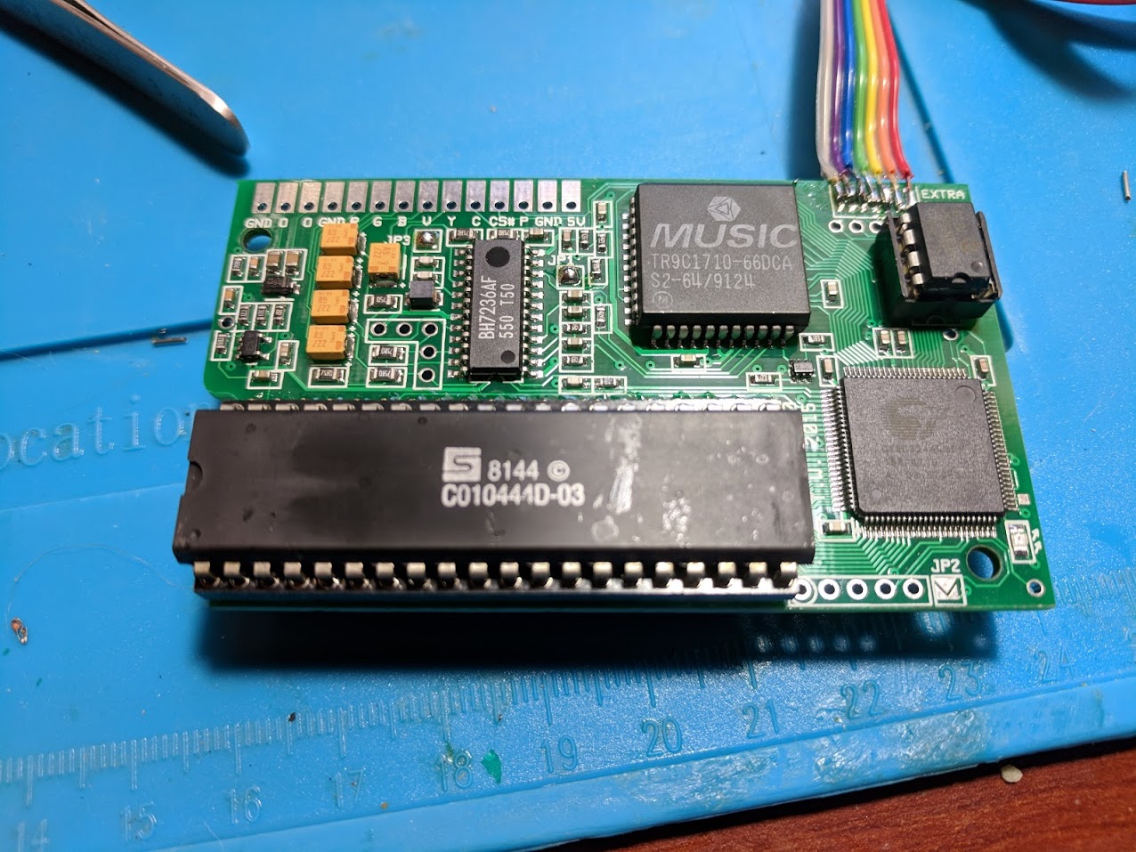
Now solder the 40-pin machine socket header into the PCB, and put the 40-pin graphics chip you removed from the Atari 2600 into the socket, make sure the orientation is the same as it was when you removed it from the Atari 2600.
Installing the 2600RGB board
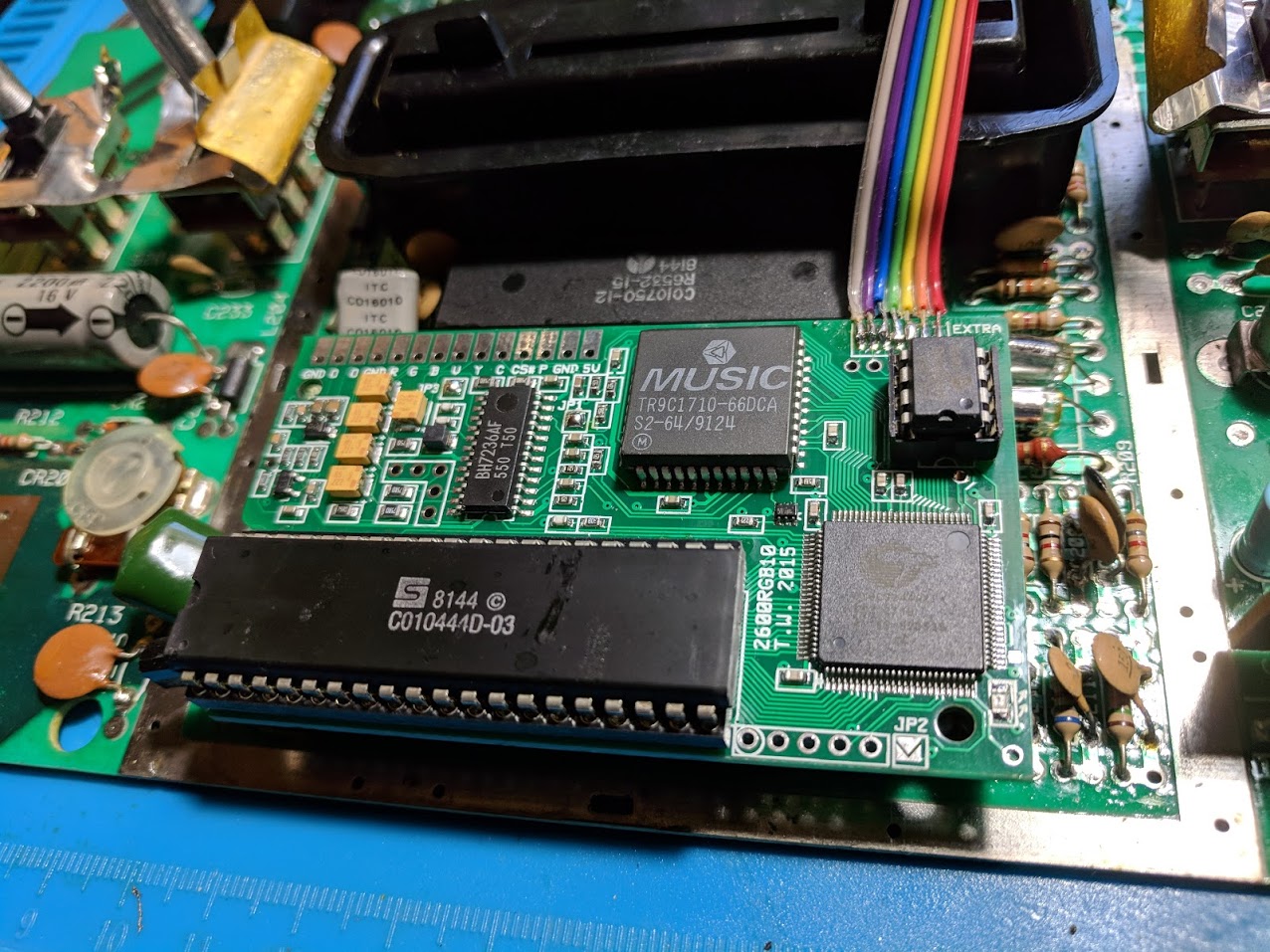
Begin by pushing the 2600RGB PCB into the empty socket, it will require a good amount of force to go in.
Now we’ll connect the 7-pin ribbon wire to a few spots on the board. This is an optional step. If you don’t want to add additional buttons to your controller to do things like reset the console or select game modes you can skip this and just remove the ribbon cable.
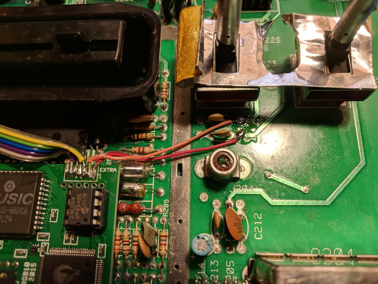
Connect the first wire to the reset switch on the console, you may need to use a multimeter to find out where it’s connected if your console is different from mine. Then connect the second pin to the select switch on your console.

The remaining five wires connect to the left controller port. Using pin numbers from the 2600RGB PCB: pin three is right, pin four is left, pin five is down, pin six is fire, and pin seven is up. You can solder to either the top or bottom of the controller port, but I chose the top for a slightly cleaner installation.
Installing the voltage regulator
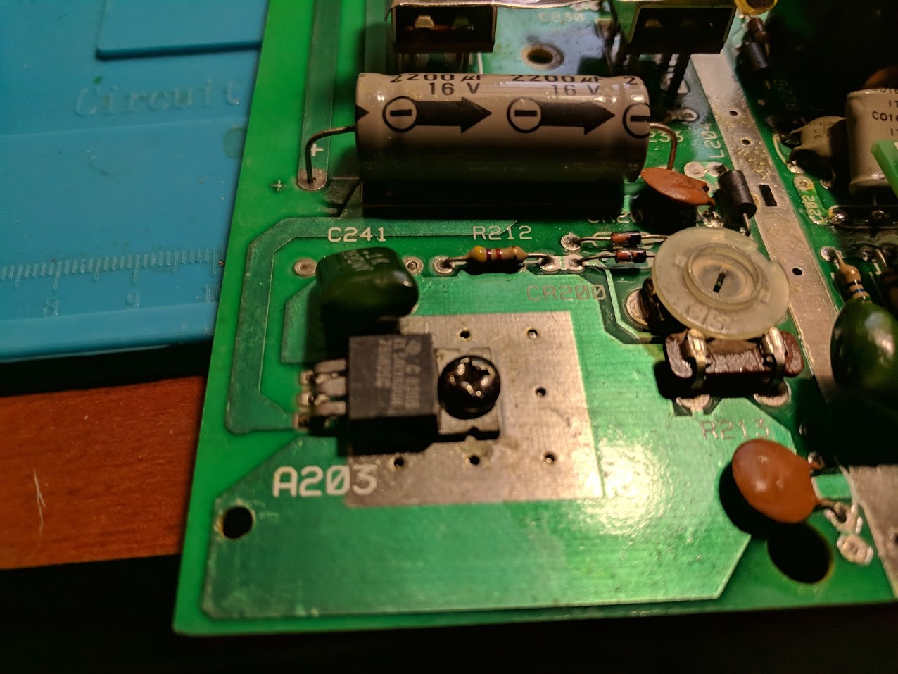
There is a small linear voltage regulator in the bottom left corner of the Atari 2600. Remove it from the PCB by unscrewing it, and desoldering it.
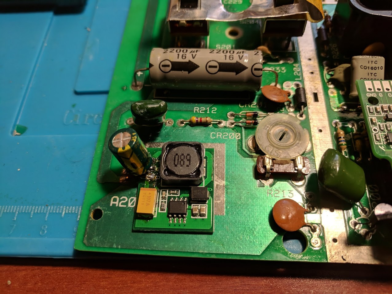
Then solder the right angle 3-pin headers to the voltage regulator, and through the holes that the voltage regulator had. Make sure it is in the correct orientation by using a mulimeter to make sure the ground pin on the regulator is connected to the metal pad underneath. You’ll also want to solder the electrolytic capacitor between the ground pad and voltage output pad (the ground pin lines up with the side of the capacitor with the stripe).
Preparing the Atari 2600 outer shell

To have the new video output ports accessible from outside of the console you’ll need to drill some holes into the console using a step drill bit. I chose to make my holes in the back side of the bottom part of the shell.
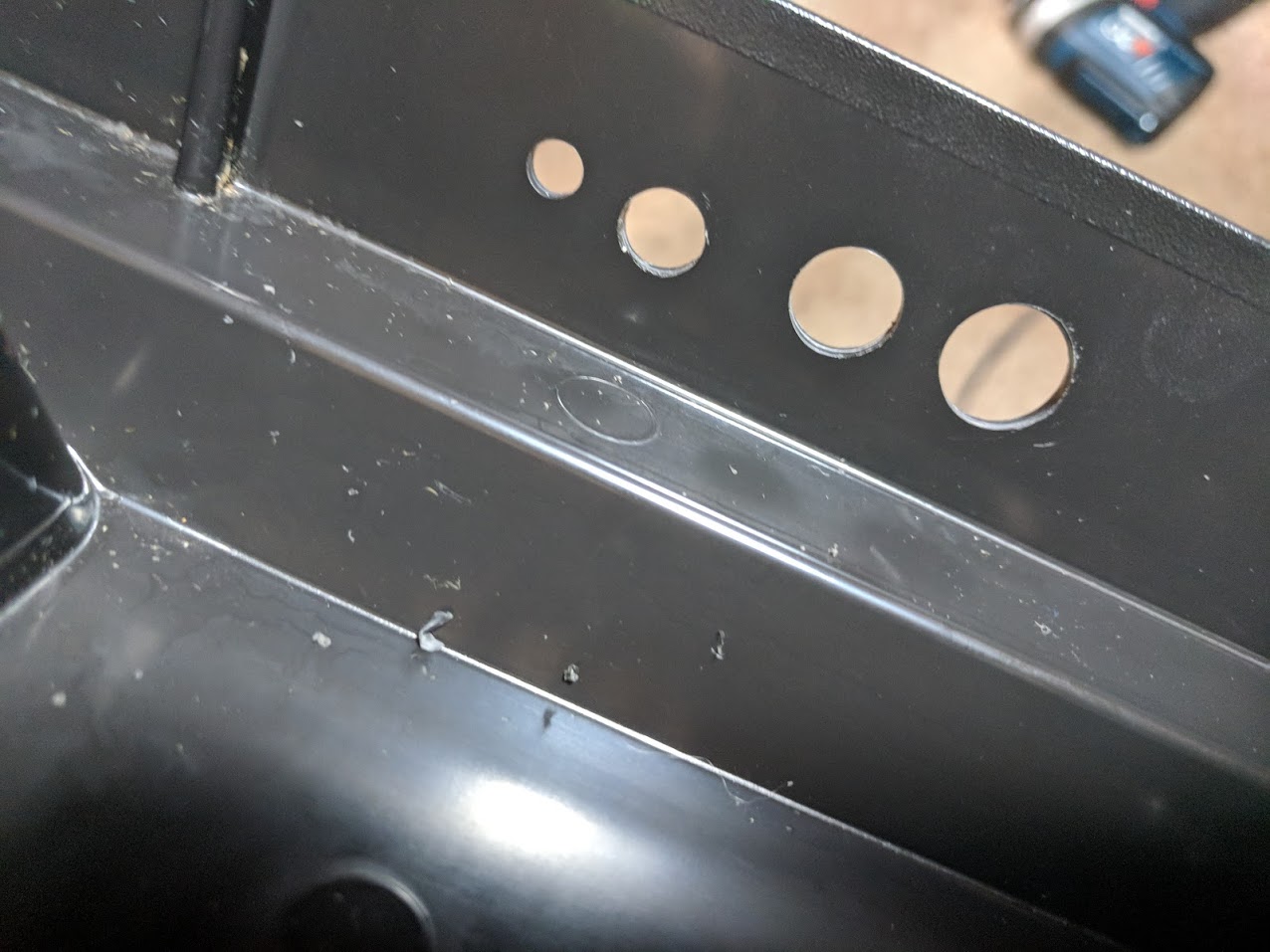
Two larger 12mm holes were needed for the 8-pin mini-DIN and S-Video connectors. If you aren’t going to be using S-Video you don’t need to drill a hole for its connector. A slightly smaller hole is needed for the 3.5mm headphone jack, I’m pretty sure I drilled a 6mm hole for this. Finally a smaller 3mm hole was used for the color palette button (also not completely necessary).
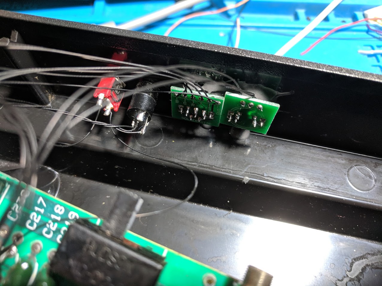
With the holes in place you can put all of the plugs into place. The button and 3.5mm jack have screw on mounts. The other two connectors need to be fixed into place using epoxy.
Connecting everything to the Atari 2600
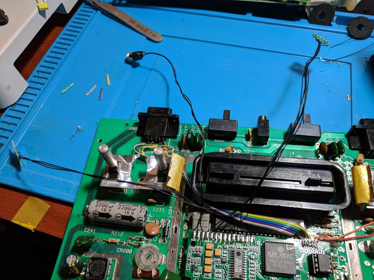
Now you’ll want to connect all of the connectors to the 2600RGB PCB. I used some 30 AWG kynar wire for this. The pads on the 2600RGB PCB have labels which match the labels on the connectors for the most part.
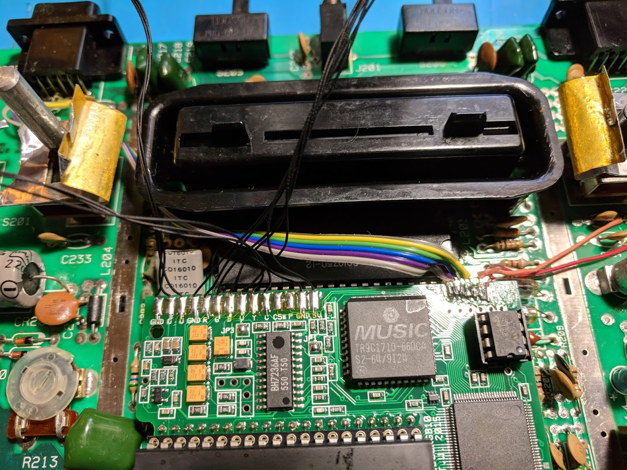
For the 3.5mm audio jack there are two pads labeled “O” which are for the left and right channels on the 3.5mm jack, along with a ground pad.
For the 8-pin mini-DIN connector the pin labeled V connects to the pad labeled CS#, and not the pad labeled V (although both seem to output video correctly through my OSSC).
The palette switch connects between the pad labeled P and a ground pad.
There are a few jumpers you’ll need to connect on the 2600RGB PCB:
- Close JP1 for 75 ohm sync (otherwise it is TTL sync)
- If your console is French SECAM, close JP2
- Close JP3 if your console is NTSC
Now you can put the metal shield back onto the console. You’ll need to cut some holes into it so that the wires can come through.
Above is a picture showing all of the connections after they have been connected to the Atari 2600’s case.
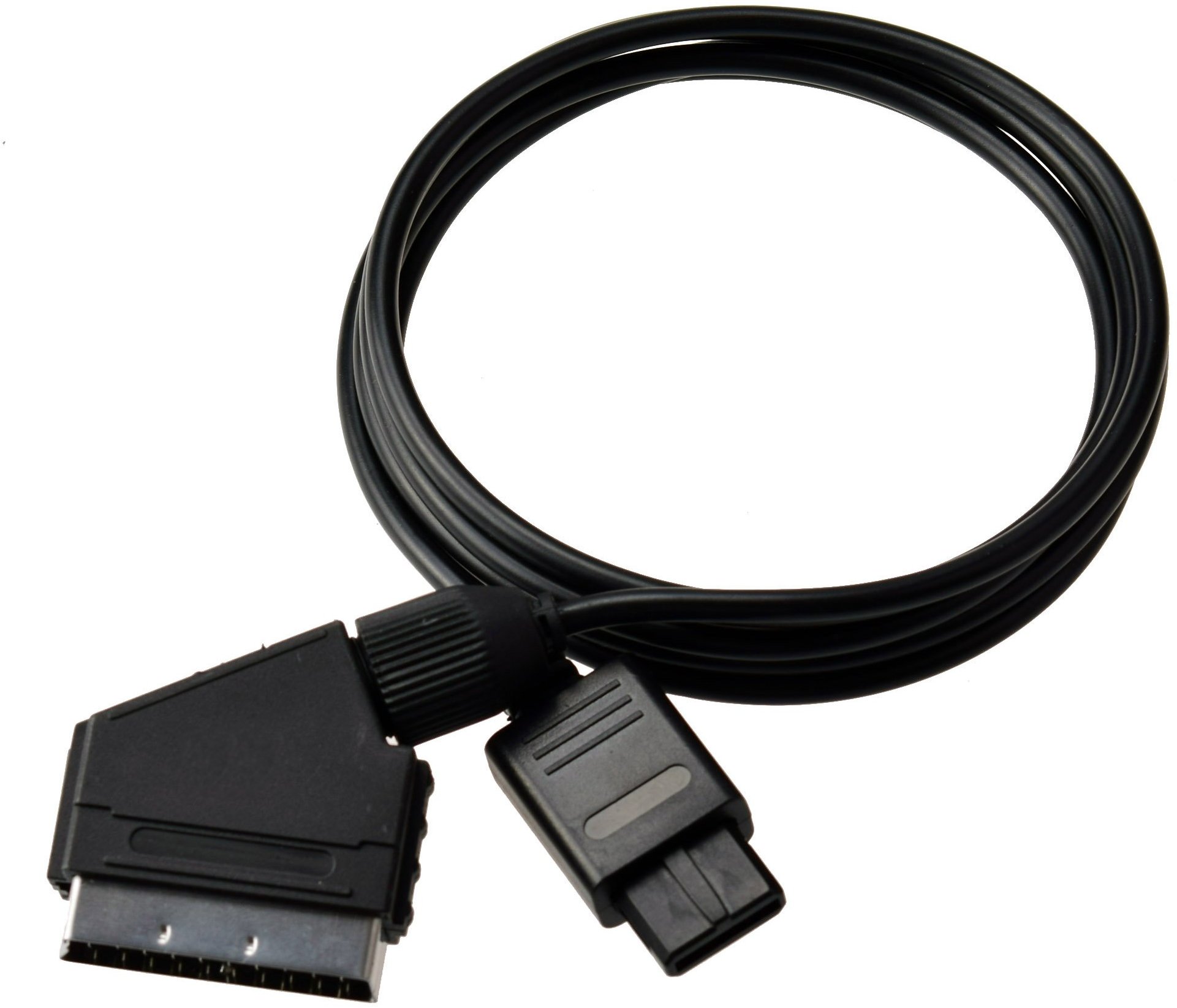
Making an 8-pin mini-DIN to RGB SCART cable
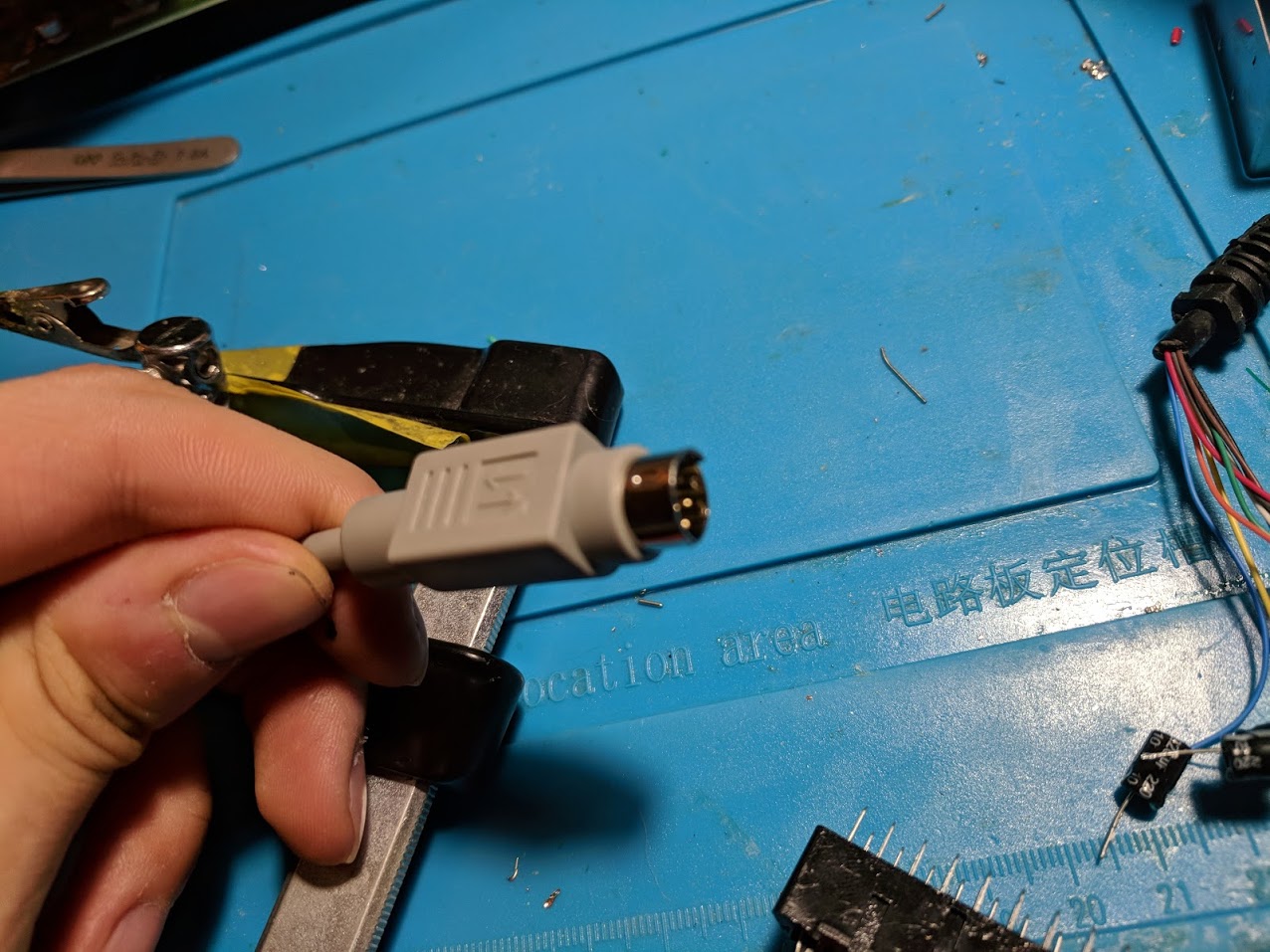
You can purchase an 8-pin mini-DIN to RGB SCART cable from the same people who make the 2600RGB board, but it is out of stock at the time of writing this post. Because of this I made my own cable using a cheap 8-pin mini-DIN cable along with a RGB SCART connector taken from a cheap RGB SCART cable.
- Orange wire is ground (female pin 4)
- Red wire is composite sync (female pin 3)
- Yellow wire is for 5V and is connected to that 180 ohm resistor (female pin five)
- Green wire is for blue (female pin 6)
- Blue wire is for green (female pin 7)
- Purple wire is for red (female pin 8)

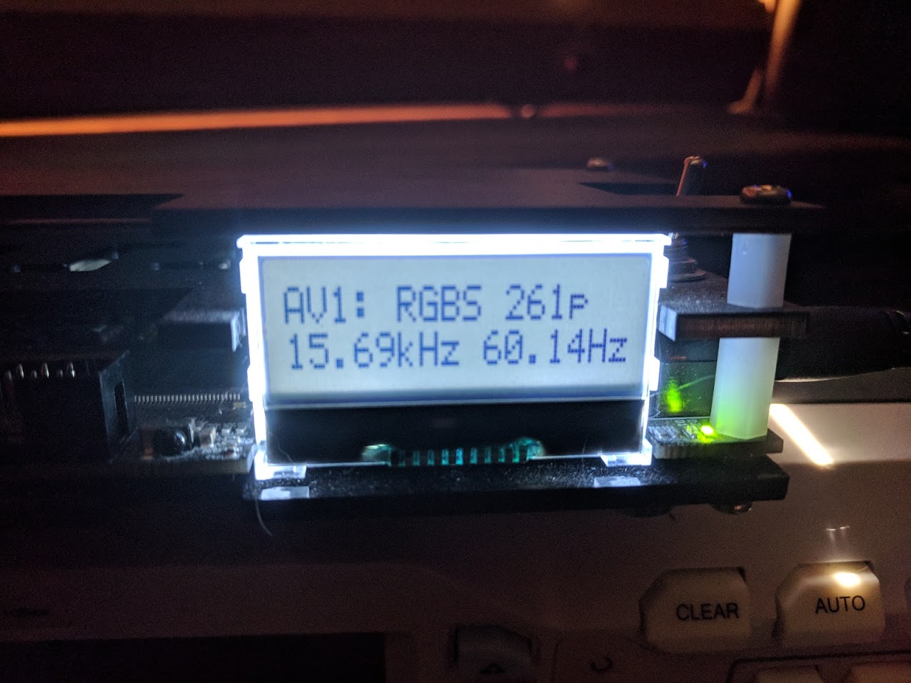
Mod results
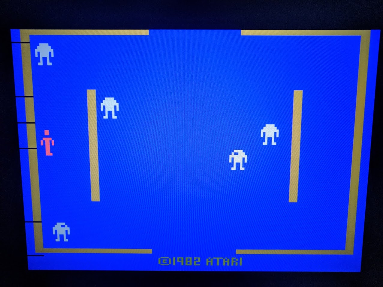
I didn’t have the chance to see what the Atari 2600 RF video output looked like, but the RGB video output looks very good. Above is a picture I took with my phone while playing Berzerk through my OSSC. The video quality is on par with what you’d get using an emulator. Since I prefer playing games on original hardware this is exactly what I was looking for.
I’d like to mention that this mod is actually pretty easy to install. A lot of really easy connections, nothing is tricky. The problem with this mod is that it’s really time consuming, so make sure you have a good amount of time set aside to install he 2600RGB.
Do you have system for sale?
Not at the moment.