V12 Modbo modchip installation diagram
The very first revision of the slim PlayStation 2 was the V12. They were found in most of the SCPH-7000x and all SCPH-7001x models. They retain full PS1 backwards compatibility, and require some form of a laser fix. Matching console model numbers and board numbers are listed below.
You can find the model number on the sticker on the bottom of the console, and the board number is printed on the PS2 main board if you take apart your console. Note that there can be multiple board numbers within a specific model number.
- NTSC-J (Japan):
- SCPH-70000 (GH-035-11)
- SCPH-70006 (GH-035-11)
- SCPH-70007 (GH-035-11)
- NTSC-U/C (USA)
- SCPH-70011 (GH-035-21)
- SCPH-70012 (GH-035-21)
- PAL
- SCPH-70002 (GH-035-61)
- SCPH-70003 (GH-035-61)
- SCPH-70004 (GH-035-61)
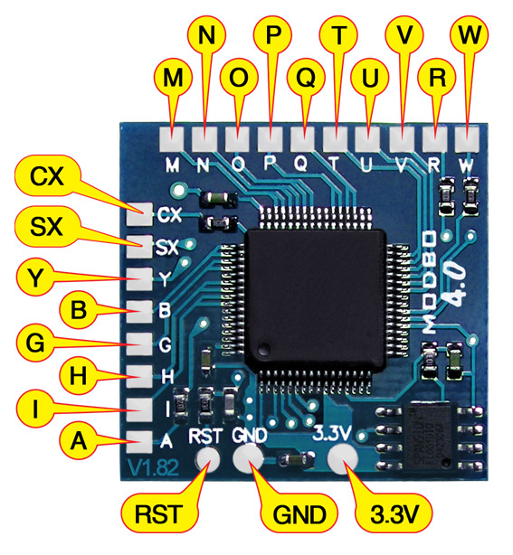
Note that there are multiple versions of the Modbo modchips available, but the installation diagrams are all the same. Some example versions are Modbo 3.0, Modbo 4.0, Modbo 5.0, and Modbo 750.
For more information about Modbo modchips click here, for more information about PS2 modchips in general click here.
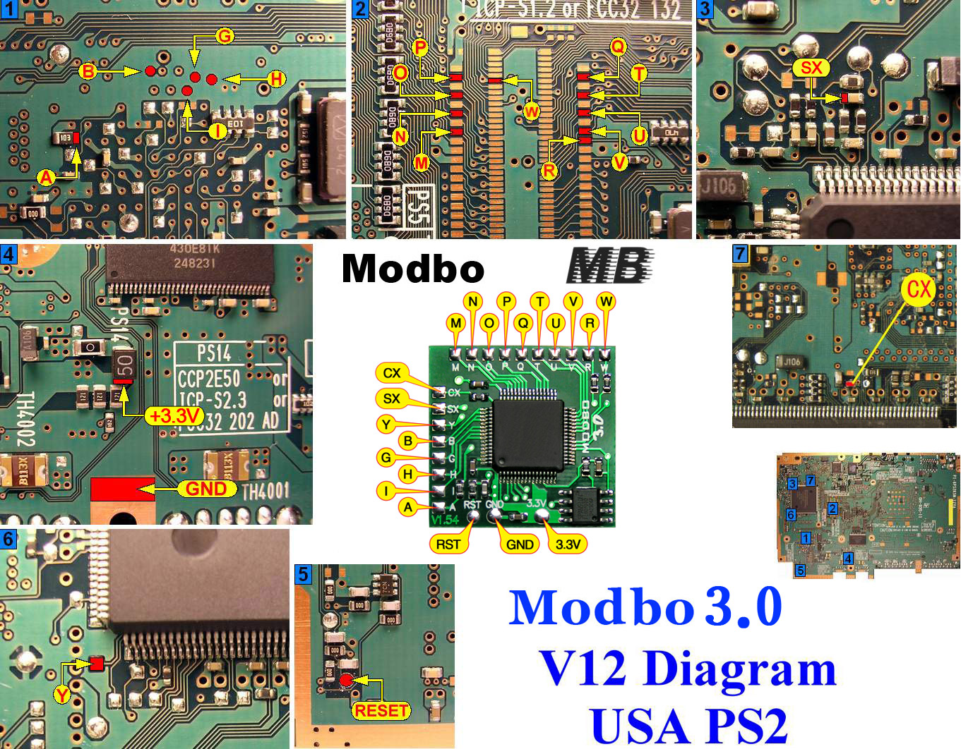
V12 Modbo installation diagram
V12 laser fix diagrams
There was a defect in the design of the V12 console that can cause the laser to burn out when playing back games once a modchip has been installed. There are three main fixes out there. I recommend installing the summ0ne’s fix at a minimum, but ideally you’d want to install the PIC fix. I don’t recommend the diode fix.
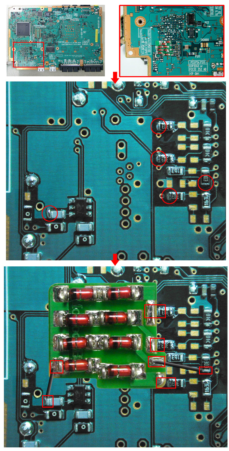
- summ0ne’s fix
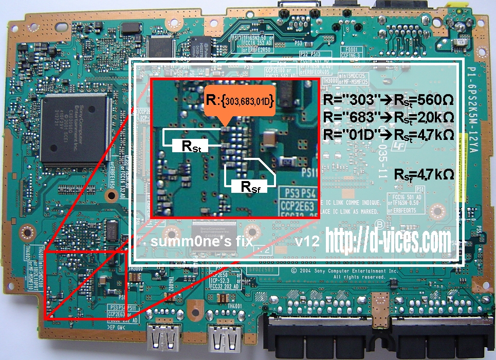 This fix involves soldering two resistors to your PS2’s main board. Read the label on the resistor marked R:{303,683,01D}. Based on that value install the corresponding Rst resistor, and then install the 4.7k-ohm Rsf resistor.It’s a very easy and cheap fix that reduces the maximum power doing into the laser preventing burnout.The disadvantage to this fix is that it can reduce the effectiveness of a worn out laser (because the laser may actually need a higher voltage as it wears out).
 - Matrix PIC fix
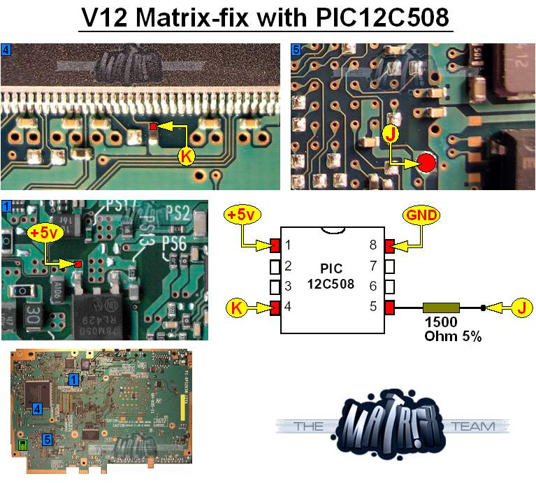 This fix involves soldering a programmed PIC12C508 chip, along with a 1.5k-ohm resistor, to your PS2’s main board. The PIC will sense when the disc mechanics (mechacon) controller crashes, and shut off the system when that happens so the laser won’t get burned out.This is a great fix, since it only interacts with the system when things go wrong, and not all the time. The disadvantages to this fix is that it costs the most, and it could potentially shut off your system when you’re playing a game. It can also be more time consuming to find the right resistor value if the 1.5k resistor doesn’t work.To test the PIC fix installation connect pin 4 to GND instead of point K. If the system turns on and then off about 3 seconds later then the installation is good. If the system never turns on (or the red system light doesn’t even turn on) then that means the resistor value is too low (try a 2k resistor). If the system doesn’t turn off then you might need to try a lower resistor value, or you might have an issue with your chip or installation.
 - Diode fix

This fix involves soldering a couple of 1N4148 diodes to your PS2’s main board. It works by reducing the voltage of the signal coming from the CD/DVD controller, which in turn reduces the amount of voltage going to the laser.I’ve heard of many cases where a system’s laser will still burn out even with the diode fix installed. Because of that I do not recommend the diode fix. It can also reduce the effectiveness of a worn out laser (because the laser may actually need a higher voltage as it wears out).
Installation tips
Here are some tips I have for you when you are soldering your chip into a V12.
- Using 30 AWG solid core wire works well for most of the points.
- Use some thicker wire for the 5V and ground wires.
- Make sure wherever you are putting your chip won’t cause any issues when putting the system back together, PS2 slims fit together very tightly.
Example installations
This section has photos of some successful installations which you can use to get a better understanding of how everything is wired and positioned. Leave a comment and I’ll add your installation to the list
- William Quade (me)

Thanks for the useful infos.
PAL SCPH-70004 GH-032-31, you can add this revision here because it worked fine.
Just a tip, I think that’s better to place the chip on the right near “caution”.
You have to use more wire but there is more room when reassembling the console.
Hello
Thanks for your info !
I put a picture of mine ps2
V12 ps2 Modbo 5.0 with summ0ne’s fix
picture
After I modified my 70006 with summ0ne’s fix, the laser motor do not spin, do you have same issue? how to solve it? thanks.
You messed something up, it shouldn’t have this issue. Remove the fix and see if it works.
Hello! Thanks for all these guides, you site is awesome! I have a PS2 slim SCPH 70010 should I follow this diagram? Thanks!
Yes, it should work. If there isn’t GH-035-## printed on the board then you’ll have to use one of the other diagrams.
Does this installation method will work on (GH-035-72) board??
Probably. You have to look at your actual board and find the points in the diagram. If you can’t find the points try another diagram.
thanks….one more thing can u plz make a blog on how to add hdd on this board !!
Hello, where can i pick up a programmed PIC12C508 chip on a PCB as shown in install videos I have seen?
The Matrix PIC fix? I could sell you a programmed board that looks like this:
It’s a little bigger than the smallest breakouts that are out there. I could also just sell you a programmed SOIC chip that you could solder to a smaller breakout PCB (there are some on places like eBay and Amazon).
Sent you an email. Thanks!
Hello, about the two resistors rst and rsf of sommOne, which are mostly wattage, thank you
1/4 or 1/2 watt resistors will work. 1/4 W will be easier to work with since they are smaller.
Thanks, your article has taught me a lot of experience.
Hi Guys, i have the SCPH-70004 GH-032-31 that is a V13 right, the laser resistor section looks the same as the V12, with R=683.
Does the V13 need the two resistors for laser voltage fix yes or no? and could i use SMT resistors intead or are they too light wattage for use.?
The V13 board doesn’t need the laser fix. SMT resistors would work if you needed to do the fix.
I did the mod on V13 with SMT and the drive acted weird and could only read original DVD video, the rest was a failure.
The mod removed again, so a few ps2 discs and a few copy’s do work now, but most do not at all and keep loading long and make strange seek pickup noises.
I think the laser is a bit snafu.
Hi William! Thank you for all the hard work you did putting this diagrams together. I’ve got my slim PS2 modded now thanks to the diagrams. An interesting note though: I have a V12 Slim PS2, model number SCPH-70012 (NTSC). The motherboard, however, did not have a GH-035-XX format motherboard. The motherboard revision was GH-032-12, which is listed as a PAL version of the V13 series. The layout was identical to your V12 diagrams so I used that, and it works perfectly. Anyway, I can share a photo of my *egregiously* bad soldering job if you want to add it… Read more »
Yeah. I got those version numbers from another website and they aren’t super accurate. Comparing the board you have to diagrams for versions that have a similar number like you did is the best way to figure out what diagram to use.
Do you sell Matrix PIC fix?
Yes: https://quade.co/store/ps2/matrix-pic-fix/
Is there an alternative point for solder point M. Mine is damaged and won’t take any solder
If you follow the trace that connects to that pad inwards you can see it connects to a via hole and then one of those smaller pads. It should also connect to the BIOS chip on the console.
I don’t have a V12 at the moment so I can’t be much more specific than that.
Thanks for that William. Point M has basically completely gone will this create an issue? I’m thinking it’s broken the circuit. Cheers
If it’s just that pad that was lifted it’s fine since it’s just a test point.
I’ve just put it all back together without the modbo so back to stick and there is no video or audio. Any idea if that pad may have been the cause? Cheers
It could possibly be the issue. It’s hard to say for sure though.
was able to use this to mod my V12 board thanks a ton
Thanks for all these guides you’ve made for various systems and chips. You’ve done an amazing job cataloguing all of this in one place. You also have the absolute BEST teardown guide for 700XX slims!
On to my question – I was curious if the PIC fix file could be written to a 12C509 instead of a 12C508, just like the MM3 can be for PS1? I haven’t worked with these chips before and want to make sure I can use a 12C509 for both before I buy a few. Thanks!
It should work on the 12C509.
I lifted the pad at cx on the board is there another spot I can solder to on the ps2 board
If you follow the trace back it connects to one of the pins on that nearby chip, and possibly a via that can be accessed on the other side of the board.
The Rsf one of my boards is a 303. It is not a 01D. Should I use a 560R?
Hello
thanks for your useful infos
i have a problem
i installed the modbo 5.0 on my v12 succsefully
when i play a backup game after the ps2 heat the game start freezing some times it doesnt load or says “please insert a playstation format disc”
can you help me about?
thanks !!!
Sounds sort of like a worn out laser.
i change the laser but nothing after 5-10minutes of game start freezing..after reset the ps2 maybe not load the game
If backups boot but stop/freeze/skip during playing it’s likely a worn out/bad laser.
Hello , possible to have the HEX for PIC Fix send on my mail ? thank you
my mother board is GH-035-21 but on shell the model is scph-70004 PAL ,
must be fixed even if not USA model ?
I’m dumb..I ordered the chip without the board..
So, I just finished my install of Modbo 5.0 with Matrix fix on V12. I think I may have killed it, but that’s ok. I was doing this for fun and for the soldering practice. However Just wanted to mention what it’s doing incase this sounds like it could be fixable. One I plug power in the light turns red. If I hit the power button it goes green for about 5 seconds then goes back to red. You ever hear of that? Once the fan started spinning then stopped. Still same behavior. I had trouble with some of the… Read more »
That sounds like the resistor for the PIC fix is the wrong value (1500 ohms is an average value that works on a lot of systems, but not all of them). Try resistor values that are a little higher (like 2200/2200 ohms).
Interesting. I’ll check it out. I might remove the resistor temporarily just to see if things work, but not run it long. Unless you don’t recommend that. How long does it take to cause the laser to burn out without the PIC fix?
You’d probably want to just completely remove the PIC fix for testing. Leaving that line floating may cause issues. The laser can burn out anywhere from immediately to never.
I have the exact same issue on a 70004. Did you solve this problem? I have only installed the modbo 5.0, didnt install any laser burnout fix. I have previously done this mod successfully so i dont know why it doesnt work this time. The other ps2 slim that i installed a modbo 5.0 in was another version and the only thing i noticed was that the place where you solder the 3.3volt connection was a bit different. The one that doesnt work looks like william quades (marked 202) and the one that works is marked 50 like on the… Read more »
Nope I never successfully got any of these installed. I did have a bit of fun attempting it though. I ordered a memory card that you can boot from and do almost all of what you could do with the chip, which worked fairly well, but I apparently damaged my disk reader during the dozen times I uninstalled it and reinstalled it so I couldn’t read disks any longer. My bad. Haven’t really messed with it since last year when I was working on this.At the time I was laid off from my job, so I had a lot of… Read more »
Too bad that you never found out what the problem was. I am suspecting that i might have killed the fuse where i soldered the 3.3v connection… I get really strange readings when i try to check its resistance. So I’ll try to find the correct smd fuse somewhere online and switch it out.
If thats not it i really dont know.
I’ve really enjoyed these mods, Great fun soldering all those tiny connections 🙂
I love you. I’m from turkey.. greetings from Turkey
SCPH-70012 is GH-035-11 not GH-035-21. Seems like a copy-and-paste error. I was looking for 5V point on this board for a different type of project and your article helped me out! Thanks!
After sucsessfull intallation of the modbo 5.0 on a V4, i’d like to modify a V12.
I see there is the need for a PIC chip. How do i get one of those?
https://quade.co/store/ps2/matrix-pic-fix/
Any opinion on the SubZero fix, or Comsoft v4 over the Matrix PIC fix?
Both good options. Haven’t used either of them though, but they appear to be just as good if not better than the PIC Fix. The PIC fix is just so convenient since I always have the PIC chips on hand for PS1 modchips.
Hello everyone, i have spch-70004 gh-032-31 board. this board already have messiah chip and diode fix, but i want to upgrade modbo. Firstly i tried remove diode fix but, after this proceses this laser work, but not disc spiner running and laser engine just vibrating, laser don’t goes any where. I didn’t break any compenent on board and i couldn’t find any missing compenent, maybe diode fix broke any component ?
You must have messed something up when removing the diode fix.
hello a question the chip to fix the laser so that it does not burn eh seen that it has the same pic12C508 number as a ps1 chip, would an MM3 be used for the V12 laser ??? that chip would fix the ps2 slim V12 laser problem thanks
No, the MM3 chip is completely different.
ok thanks, where could i get that chip for the laser thanks
I’ve been looking for it for a long time and I’m out of luck
https://quade.co/store/ps2/matrix-pic-fix/
Hey, thank you for these guides. So i did the install on a v12 board and i get the matrix logo and all the menus are working. However it will not read discs at all. I even tried disabling it witth the start button still nothing. It read them fine before i did the install. What should i check? The only thing i can think of is i lifted the I via on accident and was barely able to get the wire soldered. Is there another point i can solder to for I?
If you lifted a via then the board may be ruined (or at least need the connections that the via made repaired).