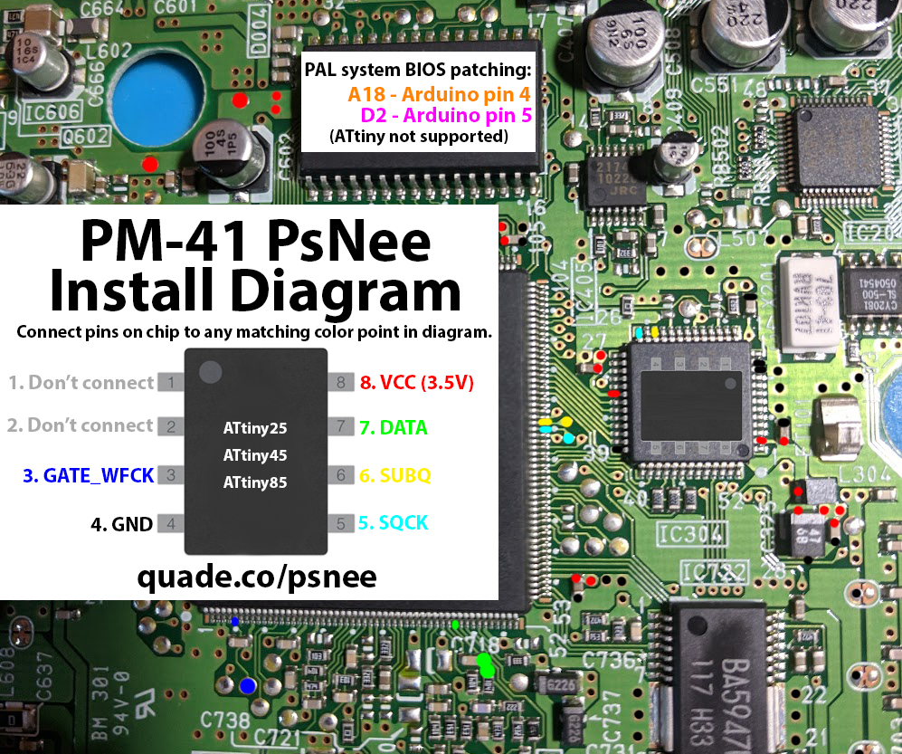
PM-41 PsNee modchip installation diagram
.Towards the end of the PlayStation 1’s life Sony released a slim model called the PSone, or SCPH-10x. Many of these systems have PM-41 boards inside, which is what this page covers. Some of the boards are PM-41 (2) and require you to use a different diagram. The model is printed on your board if you take apart your console.
For more information about PsNee chips click here, for more information about PS1 modchips click here.
PM-41 PsNee modchip installation diagram
Arduino pinout:
- Pin VCC – VCC
- Pin GND – GND
- Pin 3 – Debug TX
- Pin 4 – BIOS A18
- Pin 5 – BIOS D2
- Pin 6 – SQCK
- Pin 7 – SUBQ
- Pin 8 – DATA
- Pin 9 – GATE_WFCK
Above is the installation diagram. Just match each colored pin label in the diagram with any matching colored point on the board. There is a second image of the chip in the diagram showing a good place to position the chip.
If you have a PAL PSone system then you’ll need to use an Arduino board and connect A18 and D2. Otherwise just ignore A18 and D2.
Installation tips
Here are some tips I have for you when you are soldering your chip into the PM-41.
- Cut your wires to be as short and direct as possible.
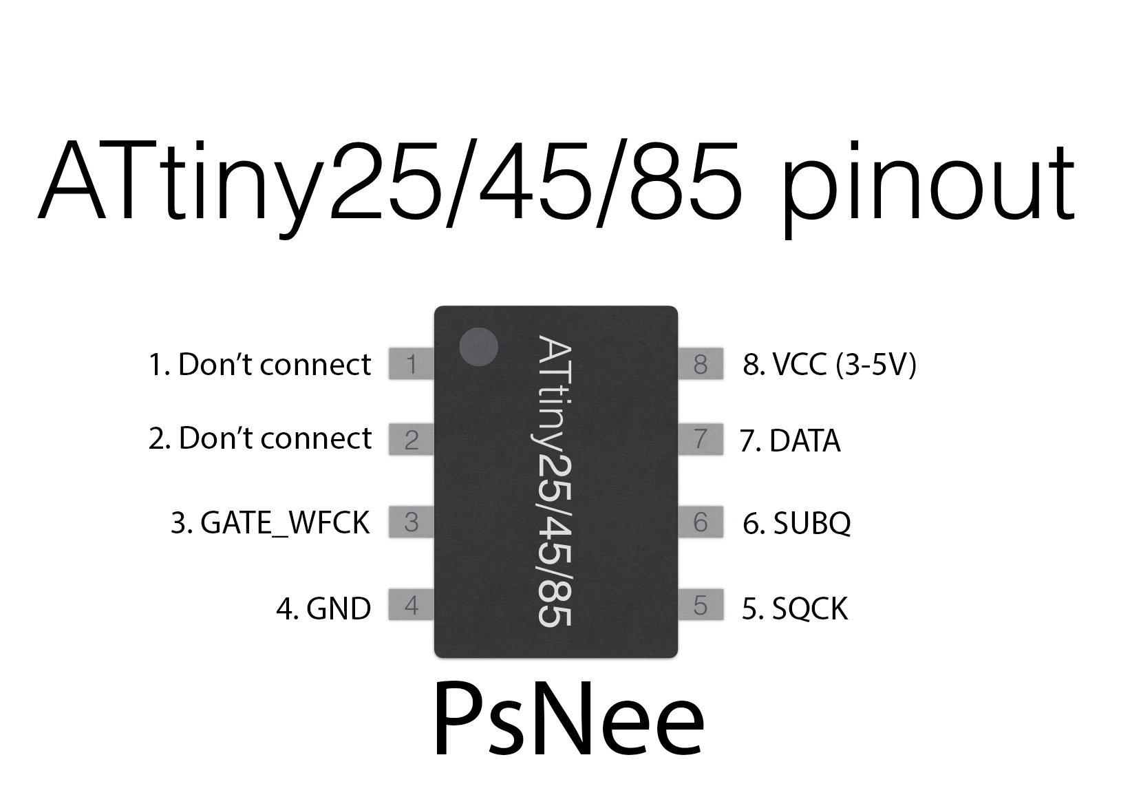
- You don’t need to connect pins one and two of the ATtinyX5 chip. Just desolder the wire.
- If you are using an ATtinyX5, or have a SCPH-101, then ignore pins A18 and D2.
- Use a multimeter to probe around for alternative VCC and GND points closer to where you position your chip for a cleaner installation.
- For the wires that go into the holes, or vias, of the board: it’s easiest to stick a small 30 AWG wire through the hole, then heat the wire and hole while adding solder.
- For DATA, be careful not to bridge solder to a nearby component, or knock the capacitor off the board.
Example installations
This section has photos of some successful installations which you can use to get a better understanding of how everything is wired and positioned.
- Nobody yet.
Successful install on a SCPH-102. Desoldered the reset pin on the Pro Mini to avoid it being squished in the on position and insulated the RF shield above using electrical tape.
Hello, from the diagram I am unsure where to solder A18 and D2. They are pin 4 and 5 on my Arduino Pro Mini but there is no corresponding coloured points on your diagram. Are you able to help me?
Many thanks
I must have forgotten to color the points in the diagram. Those two points are the same as on the PM-41 (2) diagram (which has them labeled): https://quade.co/ps1-modchip-guide/psnee/pm-41-2/
I’m thinking about programming a PsNee, but I do not own an Arduino Uno or the wires and breakout board. But I do have a TL866 programmer. Has anybody verified programming 25/45/85 on it?
Yes, a TL866 programmer will work. Just import the hex file (without the bootloader) from the Arduino build output directory, and set the correct fuses (all the defaults, except disable the CLKDIV fuse).
A18 and D12 are not marked on the diagram.
Reporting success with ATtiny85 and US NTSC PM-41. Takes a few boots to get it to work sometimes, then it’s pretty good. Thanks for the diagrams!
Hiya! Just soldered the chip to my PS One board, its the PM41. It plays USA originals, JAP Originals, but I cant get any backups to load. What could be there issue here? The backups just load the dreaded red screen or the CD player.
Thanks.
Most likely either a worn out laser, or an issue with your backups.
Ok got it, so if im able to load up JAP originals, then the modchip is working, is that right?
Also, which brand media would you recommend?
Thanks
Yes, if you can load imports the chip is working. There is no one perfect CD media and write speed. It’s all about the combination of media, write speed, disc burner, and console.
Ok, i also noticed that if I perform the swap method from a 1-1 backup, the copy does load fine.
When loading the backing it never gets to the black playstation logo screen.
Would that still be a drive or backup issue if im able to load the backup using the swap method?
It’s probably still a drive or backup disc issue.
I burned a game using a different computer and different drive, and it works now. So weird.
I had a weird problem with mm3 where I attempted to boot the console and did not notice pin 3 was not touching proper(cold joint), it blew the 7.5v rail fuse, replaced it, checked wiring(now we’ll soldered) attempted to turn on, blew another fuse, removed chip, checked for shorts or bits of solder/wire, replaced fuse, damn blew fuse again, I don’t know why it keeps blowing fuses, even without the chip, does anyone know what is happening?
You messed something up on the board at some point (probably a short somewhere).
Unfixable?
It’s probably fixable.
Successful install on a SCPH-101 – used a piece foam tape (scotch sticks on both sides), to keep the chip in place and isolated.
Hi William my new open source modchip is pretty much finished. Google Uber D D modchip for a demo of the PM41 with single wire BIOS patch. I may try and port across to PIC chip as I want to learn some assembly.
It’s always nice seeing new modchip development.