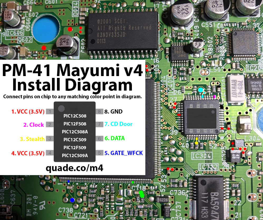
PM-41 Mayumi v4 modchip installation diagram

Towards the end of the PlayStation 1’s life Sony released a slim model called the PSone, or SCPH-10x. Many of these systems have PM-41 boards inside, which is what this page covers. Some of the boards are PM-41 (2) and require you to use a different diagram. The model is printed on your board if you take apart your console.
For more information about Mayumi v4 chips click here, for more information about PS1 modchips click here.
PM-41 Mayumi v4 modchip installation diagram
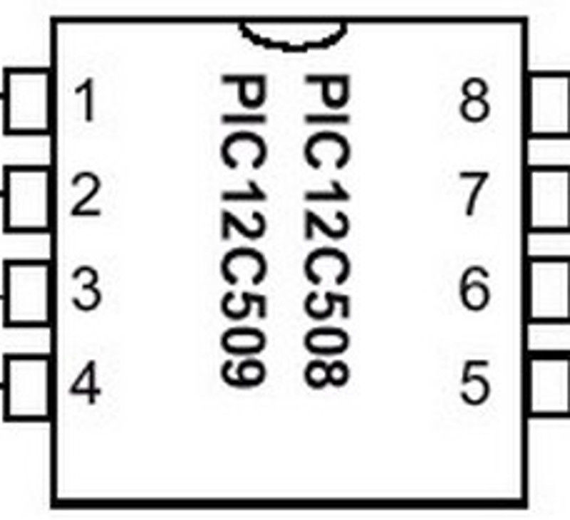
Above is the installation diagram. Just match each colored pin label in the diagram with any matching colored point on the board. There is a second image of the chip in the diagram showing a good place to position the chip.
Installation tips
Here are some tips I have for you when you are soldering your chip into the PM-41.
- Cut your wires to be as short and direct as possible.
- The high speed clock line (pin 2) needs to be especially short and carefully routed.
- Pin 3, and 6 can be tricky. Don’t push on the components with your soldering iron or they might get knocked off the board. You can use tweezers to carefully solder them back on one side at a time, the orientation doesn’t matter.
- Make sure the wire on pin 3 and 6 don’t come into contact with both sides of the component (this is especially common if you run the wire directly on top of the component).
- Don’t apply too much solder to pin 2 or you’ll bridge the pins on the chip.
- Placing the chip on top of the chip underneath pins two and seven seems to be the ideal location for the chip.

Just installed this and it works great! Thanks for the chip!
I used a Mayumi chip in a PSone (PM-41) and I noticed that I wasn’t able to play Spyro 3 at all. It got past the modchip detection but the game couldn’t boot past the first cutscenes and would frequently lose audio. It would play my other test games but I assume Spyro does something funky with the CD drive. I ended up removing the chip, flashing MM3, and reinstalling. My pin 2 run is a little longer than it needs to be because I installed the chip in between pins 5 and 8. As I discussed in a different… Read more »
Yeah, I stopped selling Mayumi v4 chips because they seem to have problems a lot of times. I believe it is due to the second pin (the one used for the Mayumi’s clock) is picking up some noise before it gets to the chip and is messing up the timing. MM3’s don’t have this problem.