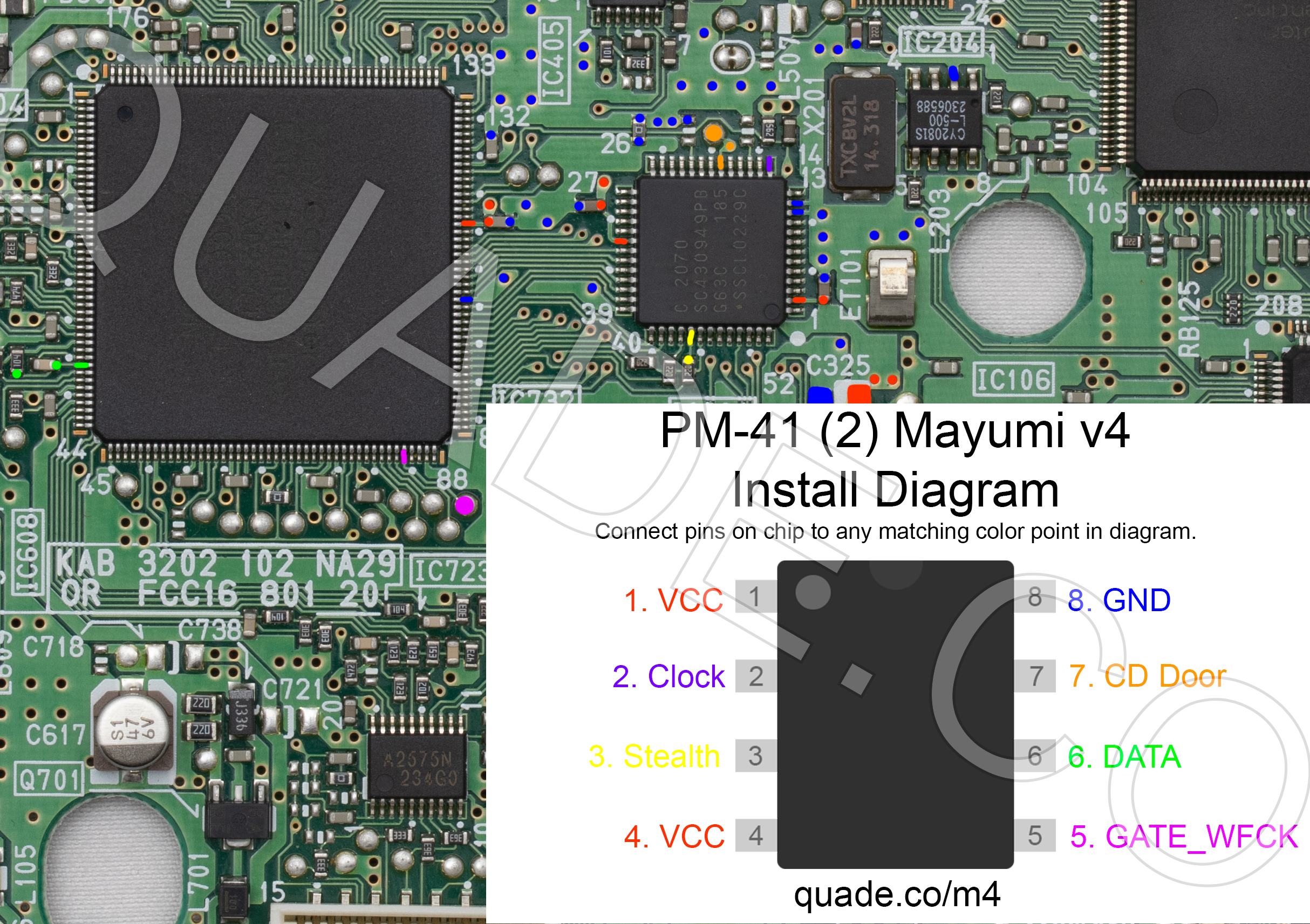
PM-41 (2) Mayumi v4 modchip installation diagram
Towards the end of the SCPH-10x PSone production Sony revised the board slightly and released the PM-41 (2) board. This page covers the installation diagram for installing a Mayumi v4 chip into the PM-41 (2).
If your board has PM-41 printed on it then you should follow the PM-41 guide instead.
For more information about Mayumi v4 chips click here, for more information about PS1 modchips click here.
PM-41 (2) board components and fuse locations
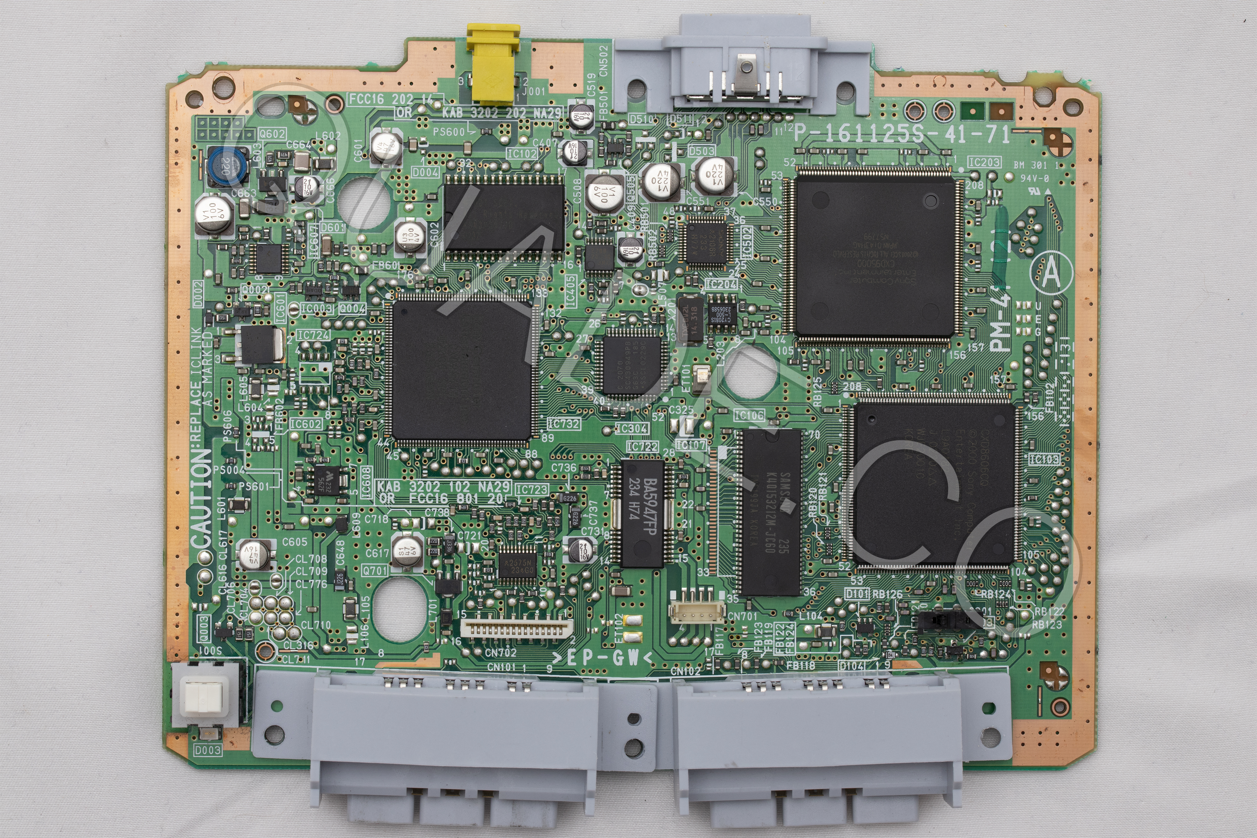
Here are a couple of photos of the PM-41 (2) board. If you click on them they’ll open in a much higher resolution format so you can zoom in on the details. This first image shows the front of the board (marked with the letter A).
This second image shows the back of the board (marked with the letter B).

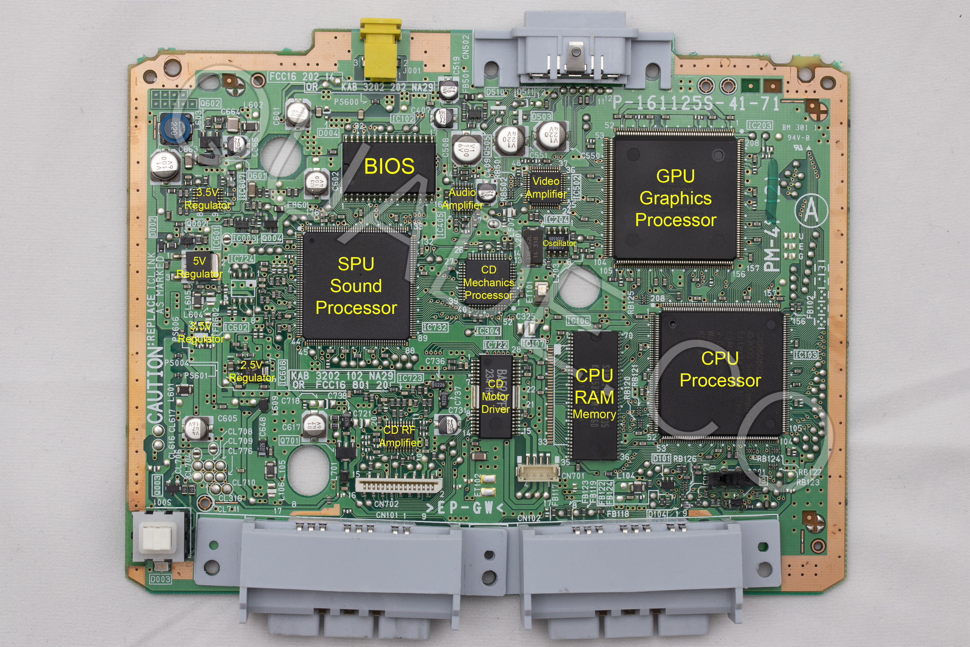
Below is that picture of the front of the board again, but this time it has labels on all of the major board components. This can be useful if you are debugging an issue on the system. For example if your video output is bad you might want to try replacing the capacitors near the video amplifier.
Another common issue people run into is blown fuses. Below is a diagram showing the locations of all of the fuses on the PM-41 (2) board. They are highlighted in yellow, with the fuse value nearby.

PM-41 (2) Mayumi v4 modchip installation diagram
Above is the installation diagram. Just match each colored pin label in the diagram with any matching colored point on the board. Click on the image for a higher resolution version. I recommend placing the modchip on top of the CD mechanics processor chip.
I have created additional diagrams primarily for colorblind people. They show one point at a time in a single color (there is a set in red, green, and blue). Because they show the entire board they may reveal more alternative points for each pin. Click on the links below to reveal the sets of images.
I’m creating these new diagrams for each PS1 board revision working from newest revision to oldest revision. It’s going to take some time, but should hopefully be more helpful than the older diagrams I had on here before.
PM-41 (2) Mayumi v4 modchip installation diagram (one diagram per pin, colored in red)
Click on the images to see them in higher resolution.
VCC: Pin 1, Pin 4

Clock: Pin 2

Stealth: Pin 3

GATE_WFCK: Pin 5

DATA: Pin 6

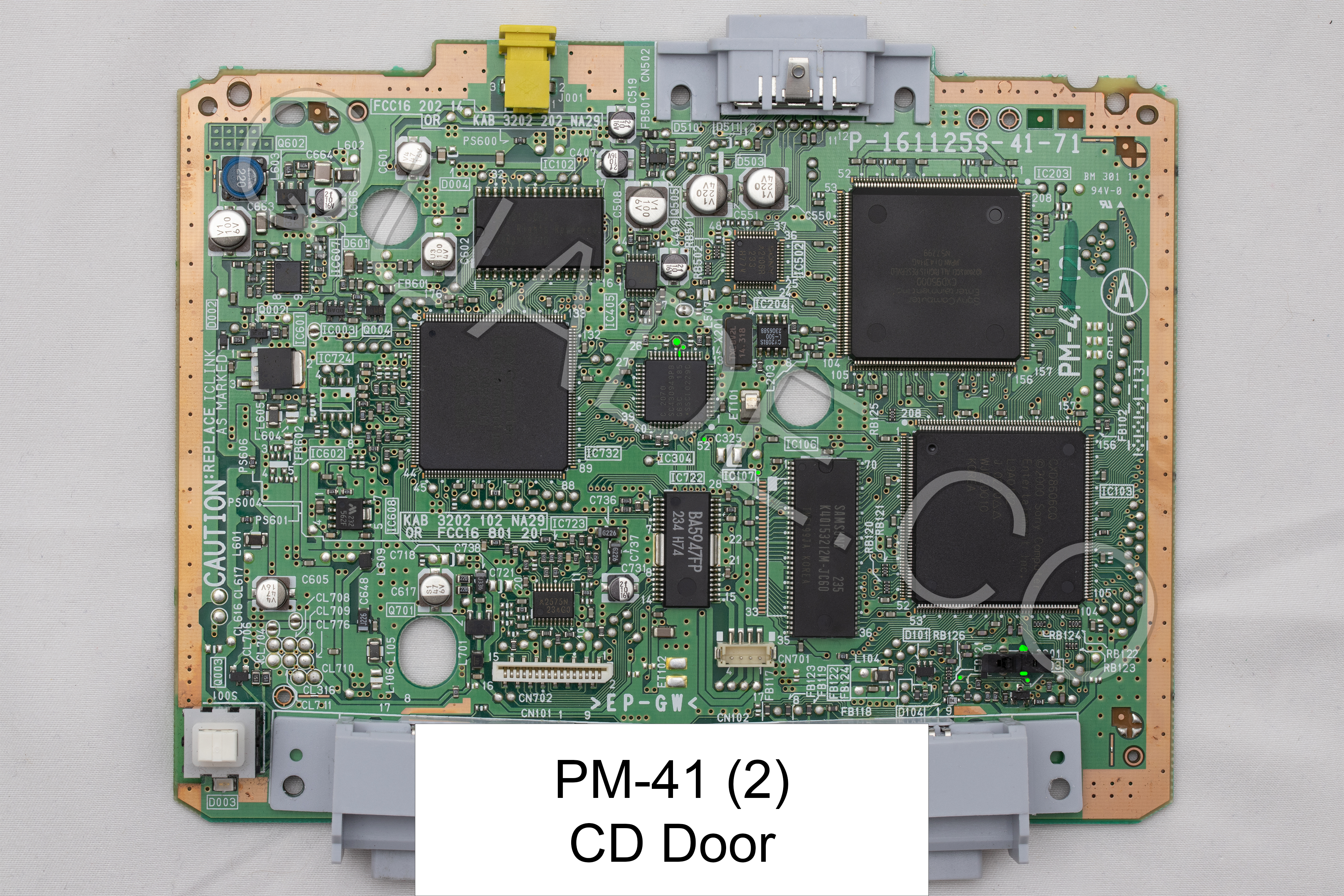
CD Door: Pin 7

GND: Pin 8

PM-41 (2) Mayumi v4 modchip installation diagram (one diagram per pin, colored in green)
Click on the images to see them in higher resolution.
VCC: Pin 1, Pin 4

Clock: Pin 2

Stealth: Pin 3

GATE_WFCK: Pin 5

DATA: Pin 6

CD Door: Pin 7
GND: Pin 8

PM-41 (2) Mayumi v4 modchip installation diagram (one diagram per pin, colored in blue)
Click on the images to see them in higher resolution.
VCC: Pin 1, Pin 4

Clock: Pin 2

Stealth: Pin 3

GATE_WFCK: Pin 5

DATA: Pin 6

CD Door: Pin 7

GND: Pin 8

Installation tips
Here are some tips I have for you when you are soldering your chip into the PM-41 (2).
- Cut your wires to be as short and direct as possible.
- The high speed clock line (pin 2) needs to be especially short and carefully routed.
- Pin 3, and 6 can be tricky. Don’t push on the components with your soldering iron or they might get knocked off the board. You can use tweezers to carefully solder them back on one side at a time, the orientation doesn’t matter.
- Make sure the wire on pin 3 and 6 don’t come into contact with both sides of the component (this is especially common if you run the wire directly on top of the component).
- Don’t apply too much solder to pin 2 and pin 4 or you’ll bridge the pins on the chip.
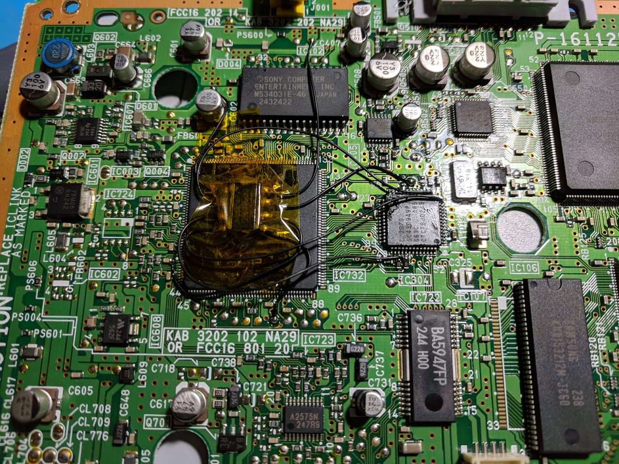
Example installations
This section has photos of some successful installations which you can use to get a better understanding of how everything is wired and positioned.
Here are some installations I’ve done on some SCPH-101’s:
Hello
Did You notice “chirping” noise? Like this?
https://instaud.io/zDF
It shouldn’t be making any new noises with the modchip installed.
It shouldn’t, but this motherboard (PAL) with ONEchip installed actually chirps, so I’ll try to figure out if other modchips works different/better. I thought about using two modchips at once.
I haven’t tested running multiple chips in a single system at the same time before, but it really isn’t something you need to do.
On its own the Mayumi v4 will not work well with PAL PSones. Non-PAL games won’t run because of the region locking in the BIOS.
The ONEchip on its own should work perfectly. It patches the BIOS to allow playing non-PAL games, and acts as a modchip to allow playing backups. For PAL PSones your only two real options are the ONEchip, or a PsNee chip on an ATmega board.
Check this thread
https://assemblergames.com/threads/psone-poor-laser-or-something-else.63587/#post-975571
More or less that’s why I am asking about Mayumi.
It may be worth trying to use a PsNee chip. At the very least they are open source so it would be much easier to fix the code if it doesn’t work properly. It would need to be the ATmega version with PAL PSone BIOS patching enabled. https://github.com/kalymos/PsNee I remember someone else having issues with chirping noises (on an American PM-41 (2)) and after they replaced the pin 6 capacitor with a new one the noise went away.They might have also used a thicker wire. I also found some forum threads where people mentioned using the other side of the… Read more »
Okay, to clarify (after long time, lol) You didn’t have any chirping on either MM3 or Mayumi on PM41(2) board?
BTW, good people here found out, that point 5 on this board is actually wrong (RFCK instead of WFCK).
https://www.obscuregamers.com/threads/psone-pm-41-2-a-modchip-problem.618/
I haven’t noticed any chirping (but where I do my soldering and testing isn’t very quiet). Thanks for the tip on point 5. I’ll update my diagrams when I have a chance.
Hi William
12f629 programme mm3 will it work on pu-41?
Yes, if you program a 12F629 with the 12F629 version of the MM3 code it’ll work as a MM3 chip.