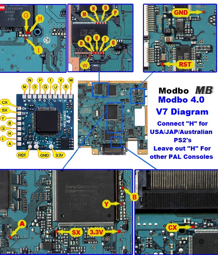
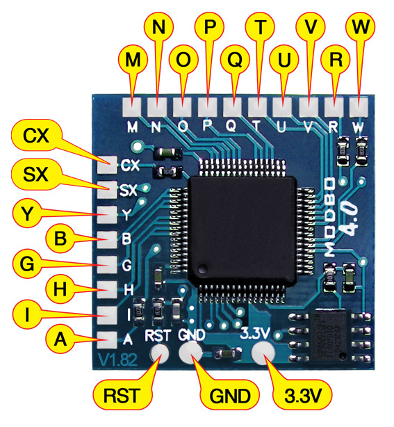
V8 Modbo modchip installation diagram
One of the revisions of the fat PlayStation 2 was the V8. They were found in many of the SCPH-3900x models. Matching console model numbers and board numbers are listed below.
You can find the model number on the sticker on the bottom of the console, and the board number is printed on the PS2 main board if you take apart your console. Note that there can be multiple board numbers within a specific model number.
- NTSC-J (Japan):
- SCPH-39000 (GH-019, GH-022)
- SCPH-39006 (GH-019, GH-022)
- SCPH-39007 (GH-019, GH-022)
- PAL
- SCPH-39002 (GH-019, GH-022)
- SCPH-39003 (GH-019, GH-022)
- SCPH-39004 (GH-019, GH-022)
- SCPH-39008 (GH-019, GH-022)
Note that there are multiple versions of the Modbo modchips available, but the installation diagrams are all the same. Some example versions are Modbo 3.0, Modbo 4.0, Modbo 5.0, and Modbo 750.
For more information about Modbo modchips click here, for more information about PS2 modchips in general click here.
V8 Modbo installation diagram
Installation tips
Here are some tips I have for you when you are soldering your chip into a V8.
- Using 30 AWG solid core wire works well for most of the points.
- Use some thicker wire for the 5V and ground wires.
Example installations
This section has photos of some successful installations which you can use to get a better understanding of how everything is wired and positioned. Leave a comment and I’ll add your installation to the list
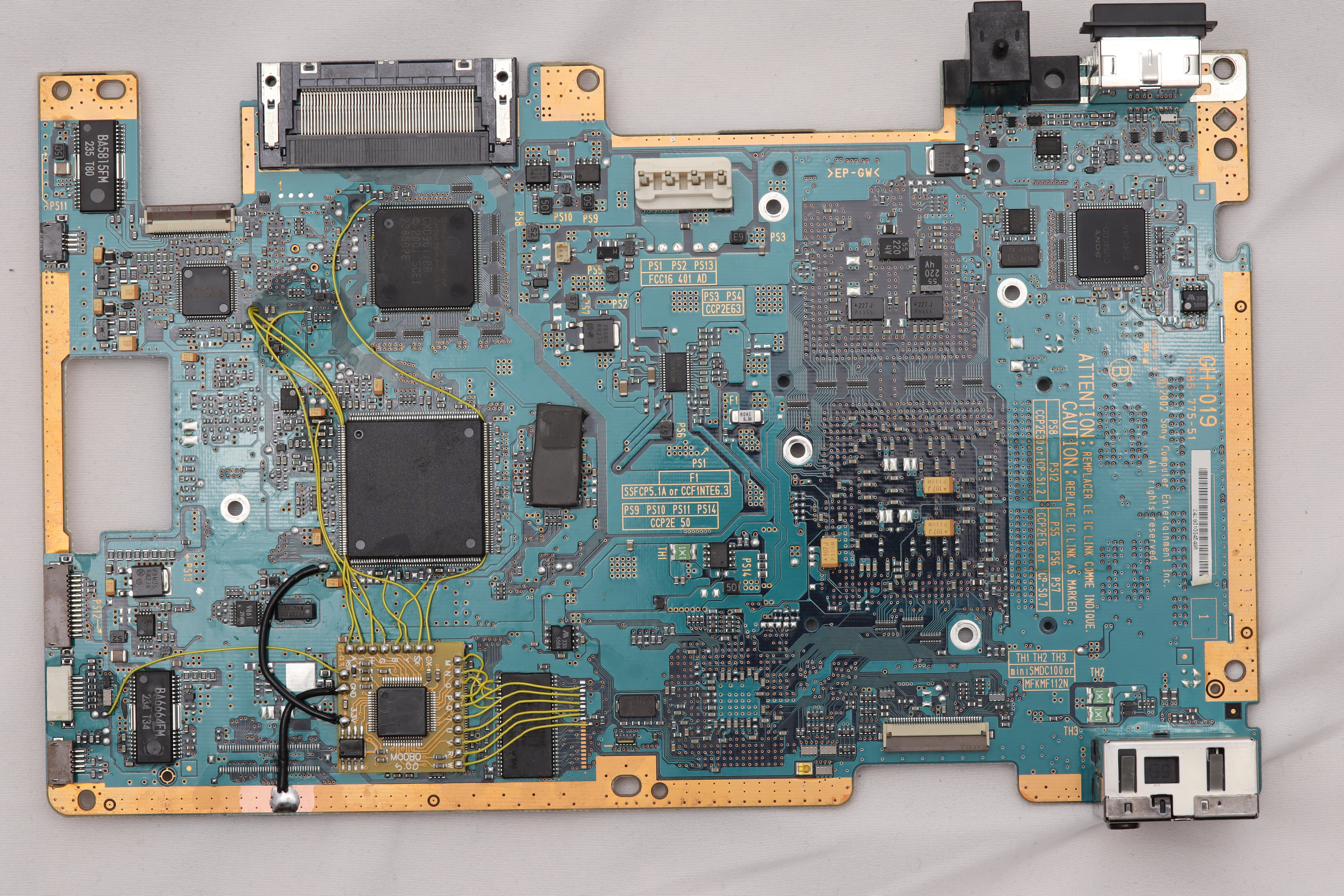
- William Quade (me)
This first one is a GH-019 board (click on the image and then zoom in to see the details). There is some solder on some additional points because I removed an older modchip and replaced it with a Modbo 5.0 on this board.
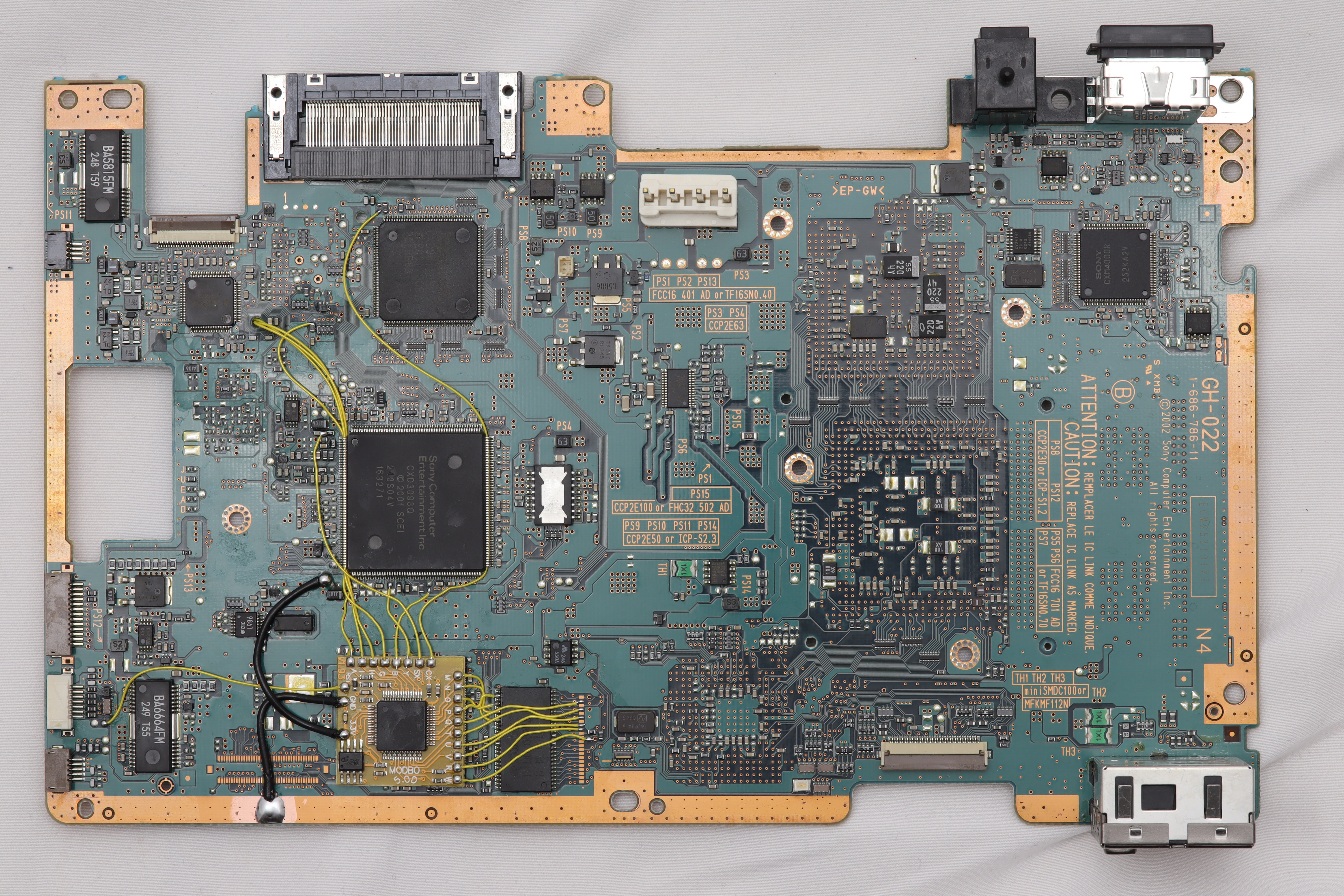
This second one is a GH-022 board (click on the image and then zoom in to see the details). You can see that even though the BIOS chip has a gap in the pins the wiring is the same.
Hi I managed to install the chip but I can’t go in the boot menu it gives me a black and blue radiant screen
The chip works because I tested one of my back up and it play the game when I hold down triangle +circle to load the menu I have that screen please help
My ps2 SCPH 39001/N
Maybe try another TV.
Yeah I got it thank you sir
Hi!
I don’t know if anyone will see this these days but I’m following this guide and I have an issue. Everything’s gone fine except the pad that you wire to B somehow pulled off the board. Is this an issue? Is there an alternate place? Or can I just do it without?
Thanks
You’ll need the B line. Look at one of the two high resolution example installations on the post (click on them to see full size, then zoom in). You’ll see that the B pad connects to one of the legs of the large chip.
Hi, this pics are amazing, do you have the reverse side of it?
No, I only took pictures of the front side.
Hi William I install the chip in my ps2 scph 39001 n I tested and it plays backup but I’m having trouble going to the chip boot menu because it’s given me a black and blue radiant screen no text everytime I reset the ps2 I got that message loading boot menu v1.00 then next screen unable to load config file!
I have a reel of 0.5mm solid core copper wire (24awg), will this be ok to use?
Matt
Probably not the easiest to work with (thicker than what’s ideal) but it’s likely workable.