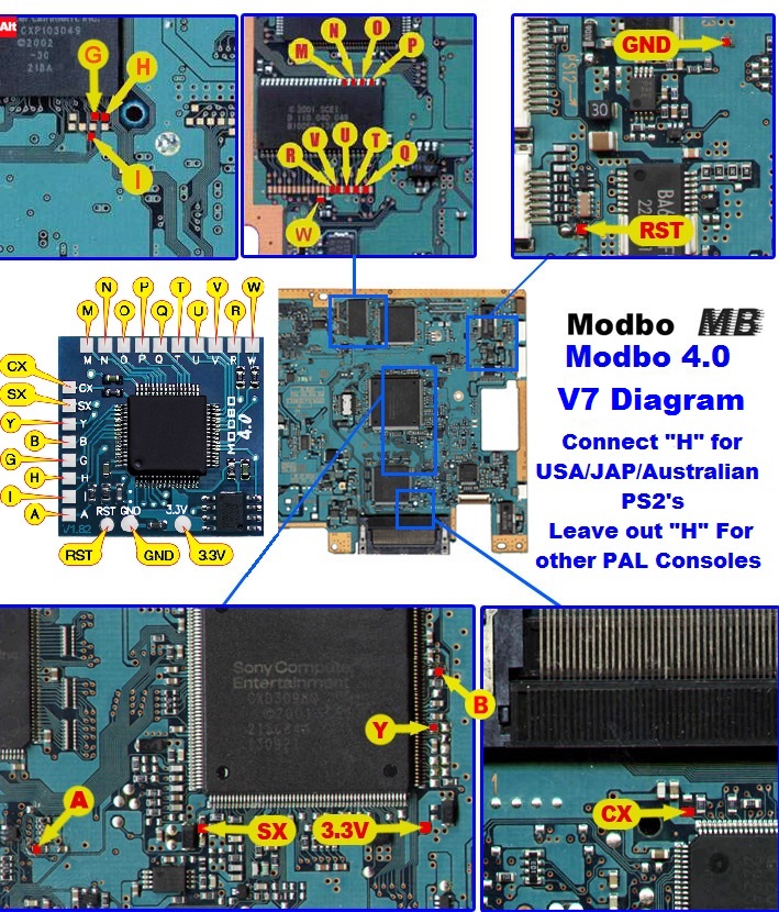
V7 Modbo modchip installation diagram
One of the revisions of the fat PlayStation 2 was the V7. They were found in many of the SCPH-3900x models. Matching console model numbers and board numbers are listed below.
You can find the model number on the sticker on the bottom of the console, and the board number is printed on the PS2 main board if you take apart your console. Note that there can be multiple board numbers within a specific model number.
- NTSC-J (Japan):
- SCPH-37000 (GH-019, GH-022)
- SCPH-39000 (GH-019, GH-022)
- SCPH-39006 (GH-019, GH-022)
- SCPH-39007 (GH-019, GH-022)
- SCPH-39008 (GH-019, GH-022)
- NTSC-U/C (United States)
- SCPH-39001 (GH-019, Gh-022)
- PAL
- SCPH-39002 (GH-019, GH-022)
- SCPH-39003 (GH-019, GH-022)
- SCPH-39004 (GH-019, GH-022)
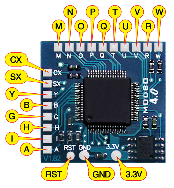
Note that there are multiple versions of the Modbo modchips available, but the installation diagrams are all the same. Some example versions are Modbo 3.0, Modbo 4.0, Modbo 5.0, and Modbo 750.
For more information about Modbo modchips click here, for more information about PS2 modchips in general click here.
V7 Modbo installation diagram
Installation tips
Here are some tips I have for you when you are soldering your chip into a V7.
- Using 30 AWG solid core wire works well for most of the points.
- Use some thicker wire for the 5V and ground wires.
Example installations
This section has photos of some successful installations which you can use to get a better understanding of how everything is wired and positioned. Leave a comment and I’ll add your installation to the list
- William Quade (me)
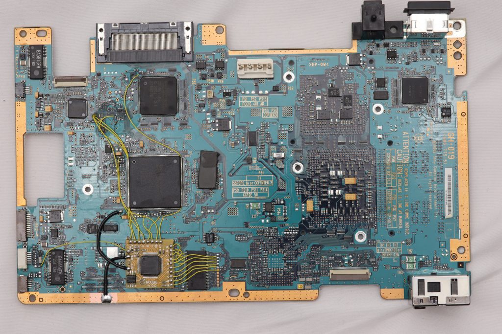
This first one is a GH-019 board (click on the image and then zoom in to see the details). There is some solder on some additional points because I removed an older modchip and replaced it with a Modbo 5.0 on this board.
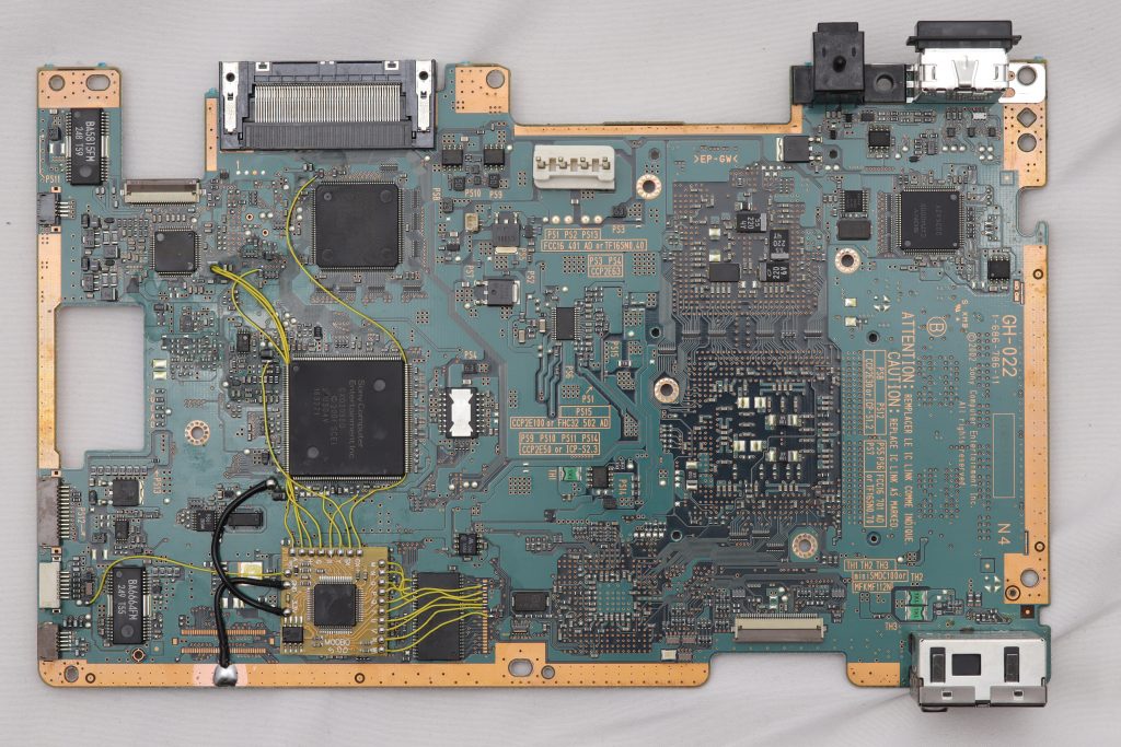
This second one is a GH-022 board (click on the image and then zoom in to see the details). You can see that even though the BIOS chip has a gap in the pins the wiring is the same.
Hi, GH-019 successfully modded on 16/6/20.
Did you bridge the caps at point SX? is this required as the track leads through both.
You can bridge them or not, doesn’t matter. They are already connected on the board.
Hello, I have had a curious problem installing modbo 5.0 on a 39001 NTSC U/C PS2. Matrix logo apears and after it shows “Loading boot_menu v.1.00…” and it remains on this screen forever. As I can see you really knows a lot about this chip, do you have any ideia if it is a incompatibility of this chip with this specific Ps2 model? I have tried 3 modbo 5.0 and no success until now. Many Thanks in advance for any type of advice.
Change boot mode to auto in the config menu (hold triangle and circle at boot).
So, I appreciate your fast reply, but I discovered the problem was not with installing the chip. This particular model did not work without one controller connected (at least this one I metioned). I have already installed modbo 5.0 in other slim ps2 and this situation does not occur like this one. That said, the curious solution to this issue was that.
Installed Modbo 5 on two PAL SCPH-39003 (GH-022) model PS2s and PS2 disc backups wouldn’t boot without the ‘H’ wire attached. So despite the instructions above, I had to include it.
Unsure if this is a difference between Modbo 4 and 5 but worth noting.
I had this too, PS2 thinks some backups are DVD Video and others it point blank refuses to load them. So are we saying that point H IS required?
H is required.
Thanks, the system is PAL but the games are NTSC. Defiantly needs the H?
Yes, H is always required. From talking to some people the original genuine Matrix Infinity and Modbo chips didn’t need H for PAL systems. But over the years the Chinese clones that are sold today lost whatever made that work, so pretty much any modchip you get today needs to have pin H connected.
I need an alternative for the RST point because I’ve broke it
Here’s a picture showing the path the point follows after that large pad. Keep in mind that these alternative points are going to be a lot harder to solder to than the normal large test pad.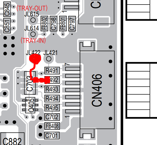
Hi, I picked up a modbo 735(branded as infinity 1.99) for a scph 39004( pal) version. Will the diagram above apply to this modchip as well?
Yes
i just installed Modbo 5 on a Pal 39004 system but there is no modbo boot up it just look like the regular ps2 boot up screen. What do you think could be at fault here?
One of the BIOS patching pins is probably not connected properly: M, N, O, P, Q, T, U, V, R, W
Hey William, thanks for replying. I’ve tested continuity and I get continuity beeps. Maybe I’ll start over though..
Also, SX is bridged on some pictures I see, I mean bridge the resistor and the capacitor and solder the wire in between. I dont have that right now. Is that needed? Model is 39004 gh-019
The SX point is used for PS1 backups so you don’t need it to get to the BIOS screen. The two parts are connected normally, so it can be easier just to solder to both (since they are already connected on the board to begin with).
Okay great. I’ll leave it as it is. Still not seeing anything when starting the PS2. Do you have tips to verify whether something is connected in the proper way? Because to be honest I don’t see anything that I can do at this point.
Hey! I also have trouble with this mod, everything is connected but no mod menu or logo. Oh and I hate those ribbon cables, looking at them damages them.
Possible to test the mod chip? I suspect its bad
You can use a multimeter to make sure the letter pads on the modchip board connect to the actual pins on the chip on the board (either directly or through other components on the board). I’ve seen some chips that have one or more pins that aren’t quite soldered in place.
Well the new modchip did the trick, finally saw the matrix menu. Powered down because I had to connect the memory card/controller station. In doing so, after having taken it apart 20 times without issues, the PSU shocked me. After doing that all I get is a black screen now. ****. I appreciate the help you’ve given so far, do you think it’s dead? I would start all over with the mod chip but I think I would at least get a video signal right? The TV does detect the ps2 upon switching it on, because it will switch to… Read more »
Never mind, it’s working again. No idea how or why though.
Hi, i did the mod as shown and get the „Matrix“ logo when power on but the disc drive does not start to spin. Eject and close are working. With an original disc in it the white thing thing on top of the drive (when the PS2 is not closed) makes a little move (0,5 cm) and then stops. You think it is a problem on the board or from the flex cables? If i have to remove the mod chip i would never again install it. Took me four evenings to install and five years of my life as… Read more »
It could be an issue with one of the ribbon cables.
Hi, thank you for the fast response. I fixed it. The motor cable was not properly connected. The PS2 now reads original discs as before but no so the backups. Maybe this is an issue of the „H“ connection as my PS2 is a PAL-one and there are different opinions if connecting it or not. But that is not a big deal as i would not use backups at all. It was only a soldering project for me and now i have enough soldered for the next ten years 🙂 For beginners i would recommend not using the same position… Read more »
Hey GH-019 is compatible with GH-22
Hey there, can I use the pad on the top instead of the bottom pad for the CX line? I used my thicker wire on accident and removed the bottom pad.
No, that’s a different point, they are not connected in any way. You’ll need to solder to the second from the left tiny pin on that chip right below that pad you lifted off.
Damn, I feel dumb lol. You can see it clear as day where that trace goes. Thank you for the quick reply!
Would it be safe to use AWG 30 wire for all points including 5G and ground, and if not what AWG wire should I use for 5G and ground?
You may have issues with 30 AWG fore the power lines, won’t damage the system, just may not work. Use something like 22-24 AWG for them.
Hello again, I have accidentally burnt the pad off on the ps2 motherboard for the Q wire, have I broken the board and if not is there an alternative point on the board to solder to?
It connects to the same chip as the M, N, O, P wires, just follow the small trace in one of my high resolution example installations, or your own board if you can see the trace. Should be the second pin from the top on the side closest to the point you messed up.
Thanks for all the detail information, I was able to install the modbo 5.0
You probably should cover the chip. It can touch the metal shielding (especially if the adhesive holding it down fails). The SX point can be connected like you described since the two components on the board are already connected.
The connecting pad where G connects to got ripped off. Is there any other other places where that could connect to (or diagrams for the console)?
If you look at some of the later diagrams like the V9/V10 diagrams the small pins on the large chip are the same and can be used as an alternate point. But keep in mind that it isn’t the easiest to solder to that chip so if you had trouble soldering to the normal point you may just mess things up even more trying to solder to the alternate point:
Hello, i have an ps2 with a gh-019 motherboard.
is there any diagrams, for solder an MODBO 750 om this, om havomgivelserne trouble ginding the correct diagrams.
thanks for any help
These diagrams will work. The Modbo 750 is basically the same as all of the other Modbo chips sold today.
Thanks i Will try find the diagram in here 👍🏻
Hi, SCPH-39004 here and i’m using the Modbo 5.0.
In the diagram it says to leave H out for PAL consoles but for mine it gave a mulfunction error while booting the game. It worked after i connected the H pin.
Idk if it’s a thing just for me but if you have the same problem it might be that.
Yes, the H pin is required for all regions. I really need to edit these old diagrams. The current Chinese clones of the old chips require H.
Hey there, I installed the modbo 5 on a scph-39001. When I turn on the PS2 the power button works but the eject button does not open the disk tray or light up but it does turn on the PS2 if I press it but nothing else. The disk tray also is not spinning. Would this have to do with the chip or with the ribbon cables?
That does sound like a ribbon cable issue (either not in all the way or damaged).
Thanks, I’m going to try to figure out if I need to replace it or just insert it all the way then.
Is it possible to ommit most of the points if I only want to use the chip for PS1 backups?
For example: Is it enough with only pwr, rst, gnd and the sx point?