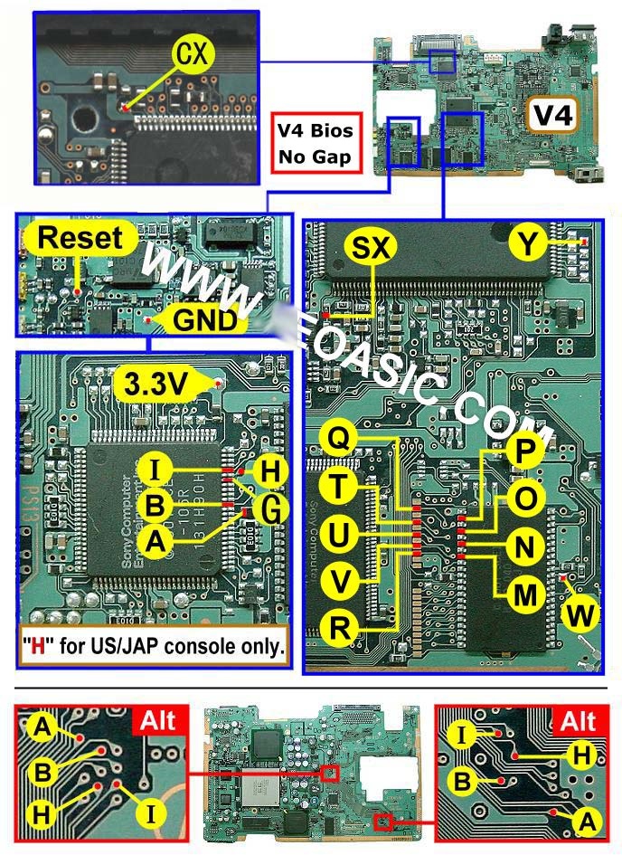
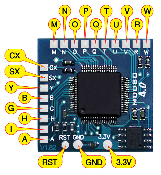
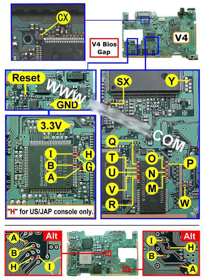
V4 Modbo modchip installation diagram

One of the revisions of the fat PlayStation 2 was the V4. They were found in many of the earliest SCPH-3000x systems, as well as the SCPH-3500x systems. Matching console model numbers and board numbers are listed below.
You can find the model number on the sticker on the bottom of the console, and the board number is printed on the PS2 main board if you take apart your console. Note that there can be multiple board numbers within a specific model number.
- NTSC-J (Japan):
- SCPH-30000 (GH-010)
- SCPH-35000 (GH-010)
- NTSC-U/C (United States)
- SCPH-30001 (GH-010)
- SCPH-35001 (GH-010)
- PAL
- SCPH-30002 (GH-010)
- SCPH-30003 (GH-010)
- SCPH-30004 (GH-010)
- SCPH-35002 (GH-010)
- SCPH-35003 (GH-010)
- SCPH-35004 (GH-010)
- SCPH-35005 (GH-010)
Note that there are multiple versions of the Modbo modchips available, but the installation diagrams are all the same. Some example versions are Modbo 3.0, Modbo 4.0, Modbo 5.0, and Modbo 750.
For more information about Modbo modchips click here, for more information about PS2 modchips in general click here.
V4 Modbo installation diagram
Some V4 consoles have a gap in the middle of the pins of the BIOS chip (near pins Q, T, U, V, R, O, P, N, and M). For those systems use this diagram:
Some V4 consoles don’t have a gap in the middle of the pins of the BIOS chip (near pins Q, T, U, V, R, P, O, N, and M). For those systems use this diagram:
Installation tips
Here are some tips I have for you when you are soldering your chip into a V4.
- Using 30 AWG solid core wire works well for most of the points.
- Use some thicker wire for the 5V and ground wires.
Example installations
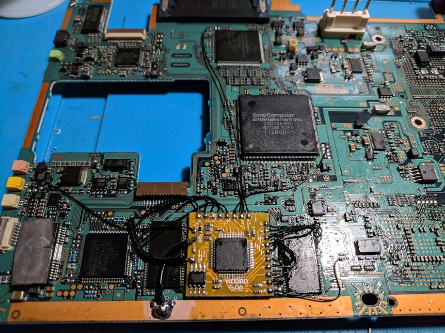
This section has photos of some successful installations which you can use to get a better understanding of how everything is wired and positioned. Leave a comment and I’ll add your installation to the list
- William Quade (me)


Hello,
Here is my install on a Fat PS2 SCPH-30001 (GH-010)
https://imgur.com/gallery/MQs0Rg1
Used stranded 30 AWG because I dont like using kynar wire (had to use it for 1 connection).
No glue on any of the wires but I feel like it came out ok.
Thanks for the well formatted website, very helpful.
Hello,
I successfully installed the modbo v5.0 on a SCPH-30000 (GH-010) too, thanks a lot for your help 😀
Hello, you can add me (LAC) to the list. It’s working, thank you.
I’ve added you to the list.
Hi guys,
Hope all is safe and sound. I’m ready to attack this install (on SCPH-30001 US) to ease my mind off from whatever happens in the world now with the novel COVID-19!
Quick question: What’s with the ALT pics from the bottom on diagram instruction sheet? (ALTernate? Are they neccessary?)
Thank you!
TangoRom
You need to connect every point on the modchip to the console. The ALT in the diagram is showing that there are multiple alternate locations that you can find some of those points.
Hi! My son’s ps2 fat is a UK version, model SCPH-30003 (GH-014) which isn’t listed and I can’t seem to find any info online ? Any info would be greatly appreciated.
That’s probably a V4 or a V5. You’d have to compare the diagrams to your actual board.
Whelp.. I really suck at this. Someone want a fun try to un f**ck it project?
Hello, I have a SCPH-30001 with serial starting U3, which I believe makes it a V4; I haven’t used it in years, instead I’ve used a slim PS2 with a Matrix I’ve had for over 10 years.
Is it indeed possible to mod this with a MODBO? If so, once your service opens up again, I may just sign up.
Yeah, it’s possible to install a Modbo chip into a V4 board. I’ll likely have the PS2 chip install eBay listing back in stock by Monday (I have a few systems on hand or on the way that need to get done before selling more install services).
hi!
i’ve installed a modbo 5.0 on a gh-013 (v4)mainboard whitout the “H” pin (ps2 pal) it right? but it doesn’t work!
can someone help me please?
With original cd is still working
Connect pin H.
ok i’l do but why in the diagram is it only for ntsc consoles?
I don’t know since I didn’t make the diagram. From my experience all pins need to be connected on all regions.
Ok thank you
Hi. Is there an alternative solder point for “point Q”? I have the no gap version of v4 motherboard. I messes up the litter copper square where Point Q must be soldered. Hope you can help me.
It should connect to one of the pins on the other side of the BIOS chip. If you find point T on the chip with a multimeter it should be two pins above that.
Is it possible to install the modbo 4.0 chip on the ps2 slim scph 90002, or should I look for another chip.
Yes it is.
Hi, can you make a zoom in the point cx in your photo? Thaks!
No, that part of my picture is too out of focus. The point is very small but it should be very obvious which one it is if you find the spot on the board. It’s right near the back of the HDD connector.
I just finished my install on the V4 board. Currently however when I boot the PS2 on the TV screen it just shows the Matrix logo and doesn’t go any further. I do hear the CD drive make a couple of very quick chirps like it’s trying to do something. I tried to hold down the triangle and Circle to get into the menu, but nada, still sits on the logo screen. Any ideas?
Sounds like an issue with one of the BIOS pins (M, N, O, P, Q, T, U, V, R, W)
Hello. I just today installed my MODBO 5.0 chip. The problem I’m having is, when I boot up my PS2 (SCPH-35001) There is a terrible distorted audio problem. It sounds like someone shoved my speakers into a blender. I tore it back down and inspected my solder points. I didn’t have any bridged leads, however, I DID have a few unstable joints. I re-soldered those until I felt good about them. Plugged my PS2 back up and still have the same issue. Any help would be greatly appreciated. Thank You
It’s hard to say what exactly went wrong. Check for any blown fuses on the PS2 board.
reflow resistor block 470 near sound DSP (if you put modbo on this)
Hello,
i’m about to istall the modbo 5.0 chip on my PS2 Fat SCPH 30004 v4.
All in the connections diagram is clear beside the ABHI pins on the motherboard. There are two different pictures of those pins in two different location of the board.
I have to use either one or the other at my choice?
Thanks for the answer, and sorry for a maybe silly question.
Sergio
They are equivalent/alternative points. You can use one or the other or the combination of the two.
Thanks William.
I thought so, but before jamming the whole stuff i wanted to be sure.
Successful install by me New_Meddle on a V4 (GH-013) SCPH-30001 motherboard!
Thank you for the guide William.
Here’s the link, sorry I didn’t include it in the other post.
https://imgur.com/a/MOfeUle
New_Meddle Hello friend, I see your image that you uploaded, I have the same GH-013 plate only that the said image does not appear, the CX point could you help me in the diagram that point does not appear is different.
Sometimes there will be component on the two pads to the right of where the CX point is in the diagram. It’s still the same spot, but just the surrounding parts look a little different.
I ended up ruining the copper at the “U” point, would there be another alternative place to solder this point?
It connects to the pins on the opposite side of the chip that has P, O, N, M points are on. The pins and pads have the same spacing/ordering.
in this case solder with the same spacing on the other side of the chip near the “W” point?
Yes, but count down the spacing from the top of the chip.
Hi my board product number is gh014 and my ps2 fat is scph-30004(its not listed probably v4)i made it as ver 4.
all pins from the diagram looks the same except “cx” pin witch I am not sure and i think that’s the problem ..its my second ps2 with modbo 5 and it doesn’t read the cd i burned but with the original games its ok..it appears disk read error with burned dvds
What does your board look like near where the CX point is? It’s not going to work without a correct CX point soldered.
Hello, thanks for all your work 🙂 I install an Modbo 5.0 on SCPH-35004 GH-012 and I have a problem. The Modbo working well but I can’t open the tray … When I manually put a disc on it it’s working good but when I push the eject button the tray won’t open. And when I manually open the tray and I push the eject button the tray closes. Do you have an idea of my problem ? 🙂 Thanks by advance
Did you accidentally knock if off of the rail or not connect all of the cables back to the board?
Thanks for your speed reply. I reflow the driver and now the console working perfectly 🙂 Thanks for all your work 😉
My board is coded GH-012, looks fairly similar to the GH-10, beside the chips on the back of the board.
I still use the GH-010 instructions?
I have a big trouble occoourred during the mod.
One of the pitch under one pin of a chip… slided away. Still thereby, bit not in his position.
Is it possibile to put it back where it was, or i just wanted the motherboard?
You lifted a solder pad? You’ll probably need to find an alternate point to solder to if that happened, assuming the system still works.
got the service manual. Found the alternative place. Thanks.
Ok, after a long fight we did it.
I just have a silly, silly question. Before reassembling the console:
Being in Italy i suppose I have a European PS2. This means i don’t have to connect the H pin, right?
You’ll need to connect pin H. It is required for the Chinese clone modchips that are sold today.
is 18awg ok for the 5v and ground connections? i stripped some from a power supply connection.
Yes