V3 Modbo modchip installation diagram

One of the revisions of the fat PlayStation 2 was the V3. They were found in many of the earliest SCPH-3000x systems. Matching console model numbers and board numbers are listed below.
You can find the model number on the sticker on the bottom of the console, and the board number is printed on the PS2 main board if you take apart your console. Note that there can be multiple board numbers within a specific model number.
- NTSC-U/C (United States)
- SCPH-30001 (GH-006)
- PAL
- SCPH-30002 (GH-007)
- SCPH-30003 (GH-007)
- SCPH-30004 (GH-007)
Note that there are multiple versions of the Modbo modchips available, but the installation diagrams are all the same. Some example versions are Modbo 3.0, Modbo 4.0, Modbo 5.0, and Modbo 750.
The V3 board revision may not be compatible with the newer Modbo 4.0/5.0/750 chips being sold today.
For more information about Modbo modchips click here, for more information about PS2 modchips in general click here.
V3 Modbo installation diagram
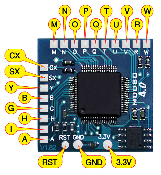
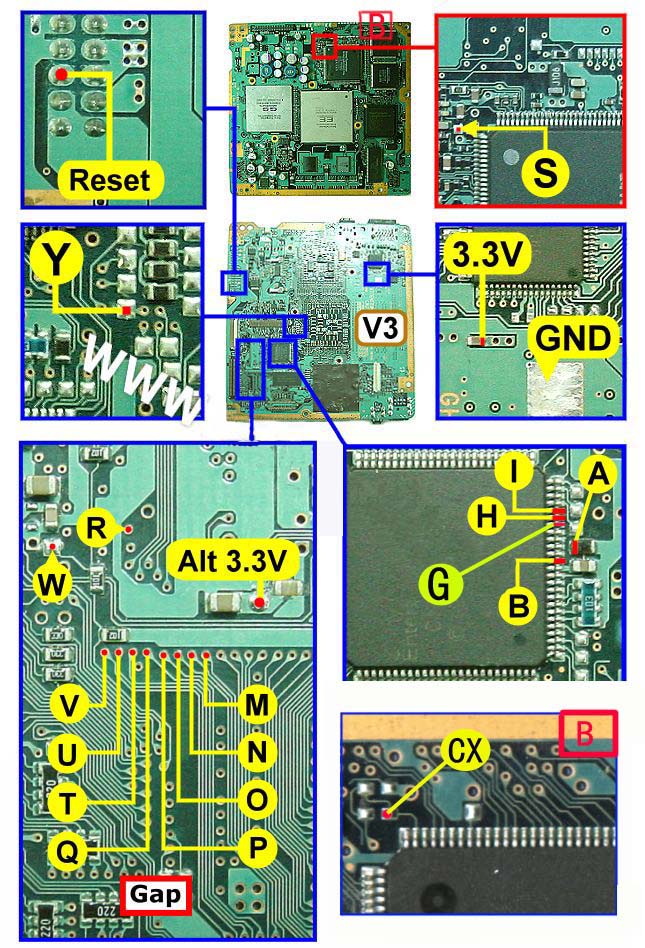
Some V3 consoles have a gap in the middle of the pins of the BIOS chip (near pins P, O, N, M, Q, T, U, and V). Use the BIOS GAP part of the diagram for those systems. If there isn’t a gap in the pins then use the BIOS NO GAP part of the diagram.
The diagram below says it’s for a Japanese system. The same diagram works for American and PAL systems if the H pin is not connected.
Below is another diagram that is for the V3 board.
Installation tips
Here are some tips I have for you when you are soldering your chip into a V3.
- Using 30 AWG solid core wire works well for most of the points.
- Use some thicker wire for the 5V and ground wires.
Example installations
This section has photos of some successful installations which you can use to get a better understanding of how everything is wired and positioned. Leave a comment and I’ll add your installation to the list
- Nobody yet.
Hello! Thanks for your guides, very helpful. I have installed a Modbo 5.0 on a SCPH-30003 (GH-007) and it works great. I’ve attached a photo.
The differences to your guide were;
Hey James, I just did Modbo 5.0 install on a v3 SCPH-30004 GH-007 board, but when I power on the console I get the Matrix screen and nothing else. I also cannot enter the Matrix config menu by holding triangle and circle. I didn’t connect the H wire as my board is PAL version. All the other letters are connected to the same points as yours. Is there any reason the H wire is connected in your picture, I thought the 30003 was PAL exclusive version? I tested the system prior the mod and even ran FMCB on it and… Read more »
Pin H shouldn’t stop you getting to the config menu, but it’ll be necessary if you want backup PS2 games to play. Older chips didn’t require it (like that were around when these diagrams were created), but the Chinese clones of them sold today do need pin H.
Oh, the impression I got from the guides was that the H wire is meant to be connected only on NTSC (and maybe Australian) consoles, regardless the Modbo version. I guess I was wrong then. I’ll see if connecting the H wire will get past the Matrix screen.
For some reason I can’t attach a pictures to my replies. It says the file type is not allowed. It’s a JPG. Maybe I’ll try on PC later. Currently on Android/Chrome.
Hello guys,
I accidentally broke the small device at the 3.3V connection point (V3).
Can someone of you tell me which type of part (resistor etc.) it is?
It would be very nice to get the possibility to fix it with a new part.
Hello! I have some doubt… First diagram, it belongs to Mobdo 3.0, and the second belongs to Mobdo 5.0. The chips are very different, because Mobdo 3.0 doesn’t have CX point as Mobdo 5.0. Which CX point is equivalent in mobdo 3.0? What is it GAP? How do I know there is GAP? Thanks
Just completely ignore the Modbo version. If your chip has a CX point solder it to the CX point. If your chip doesn’t have a CX point don’t solder it.
Some V3 consoles have a gap in the middle of the pins of the BIOS chip (near pins P, O, N, M, Q, T, U, and V). Use the BIOS GAP part of the diagram for those systems. If there isn’t a gap in the pins then use the BIOS NO GAP part of the diagram.
Hello
My PS2 Motherboard doesn’t have the CX point but Modbo 4.0 has one will it still work if i don’t solder it
No, you need to have the CX point connected for the Modbo 4.0 to work. Your board should have the point.
I tried to find to find the CX point but can’t find it could you send me a picture where i can find it i have a PAL Motherboard SCPH-30004
Here is a pic of where the CX point is supposed to be but isn’t
https://postimg.cc/3WKqDgxm
Could you send another picture showing the whole side of the board?
Here is a pic of the whole side of the board
https://postimg.cc/s1m0svym
I’m pretty sure your board is just a slightly different revision that must not have quite the same layout near that CX point. The chip on the board itself seems to be the same though, and if that’s the case then this path of points seem to all be connected to that second pin on the chip (I’d verify it with a multimeter first though):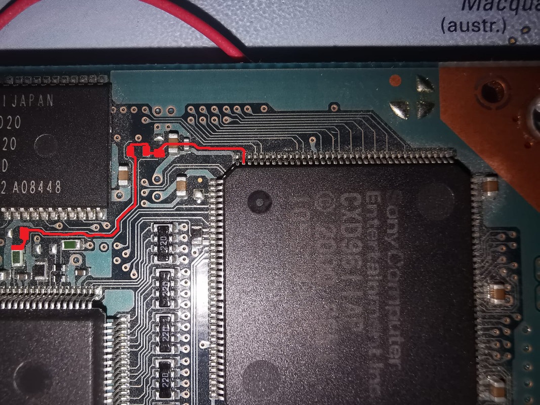
Just as i thought i wasn’t to sure about it i verified it with a multimeter and it’s connected to to the second pin of the chip and i’m not so sure where i should solder it what do you think where would be a good place to solder it
I highlighted the path so that you could choose whichever point along there that you want to use. I’d use whichever leads to the shortest wire between the point and the modchip.
Thank you very much for your help and advices 🙂
I will tell you if the modchip works so that you can add me to the list if it the modchip works
Did you manage to get this working?
so I have a v4 35001 board and I am unsure which modchip is compatible
Why are you commenting on the V3 page then? Any of the Modbo chips are compatible.