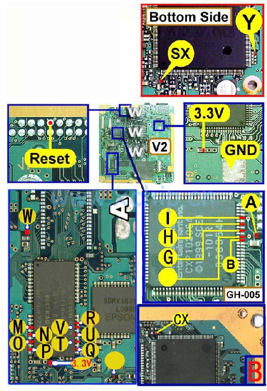
V2 Modbo modchip installation diagram
One of the earlier PlayStation 2 models that support Modchips is the V2 board revision. These also happen to be the second revision sold in the United States. Matching console model numbers and board numbers are listed below.
You can find the model number on the sticker on the back of your console, and the board number is printed on the PS2 main board if you take apart your console. Note that there can be multiple board numbers within a specific model number.
- NTSC-U/C (USA):
- SCPH-30001 (GH-005)
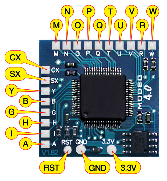
Note that there are multiple versions of the Modbo modchips available, but the installation diagrams are all the same. Some example versions are Modbo 3.0, Modbo 4.0, Modbo 5.0, and Modbo 750.
The V2 board revision may not be compatible with the newer Modbo 4.0/5.0/750 chips being sold today.
For more information about Modbo modchips click here, for more information about PS2 modchips in general click here.
V2 Modbo installation diagram
Installation tips
Here are some tips I have for you when you are soldering your chip into a V2.
- Using 30 AWG solid core wire works well for most of the points.
- Use some thicker wire for the 5V and ground wires.
Example installations
This section has photos of some successful installations which you can use to get a better understanding of how everything is wired and positioned. Leave a comment and I’ll add your installation to the list
- Nobody yet.
Im going to try and use this diagram to install if I get it to work ill post a pic.
But it will be done with a 5.0 instead of a 2.0 modbo.
I would be interested to know how it works out for you. I have a v2 PS2 (GH-005) and purchased the modbo 5.0. Some say it won’t work, others say it will.. Not entirely sure what, still taking apart my PS2. Having trouble separating the main board from an aux board. I think they might be soldered together.. Though I’d rather not desolder them unless the chip is going to work :-\.
First things first, yes, unfortunately you *do* have to de-solder the 4 pads / pins to separate the two boards. Also, make sure to get another cr3032 and replace the Sony one, while you have everything open, if you care about that. Mine was still at 3.0v. When everything was installed, it was booting to a screen that just said “loading boot_menu v1.00”. The work around was to plug a ps1 controller in. I don’t have any wired PS2 controllers to test. This isn’t the correct points for w m n o p q r t u v I used… Read more »
Yeah, there’s some difference between the picture above and my GH-005 board / what’s in your photos. For starters, the chip where M N O P connect to on your picture and my board has all the pins all in a line like a normal chip does. In the top photo it looks like a different chip is used where there’s a “separation” in the pins (they’re not all in a line) and pins are grouped into 4 quadrants, very odd. I think yours is closer to mine, though, as mine looks like that. So you tested it and it… Read more »
Sorry for taking so long to get back to you, man. Personal stuff, Corona/Covid etc. This project got put on a shelf in the meantime. I should have mentioned that I’m using the Ebay knock off Modbo 5.0D Regarding the MNOPWQTUVR #2 area, I used the ones from the DUO diagram, that chip on my board is like the one in the DUO pic. Yes, 2032 battery. Typo, sorry. 🙂 I’m using the kynar 30AWG wire like you send with the PSX chips you put on ebay. I wound up buying the cheap ~$20 usb microscope on Amazon. I have… Read more »