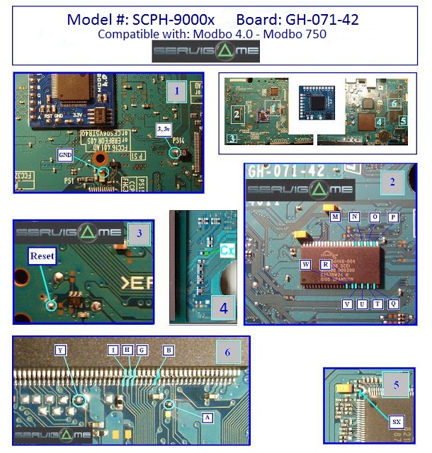
V18 Modbo modchip installation diagram
The very last PlayStation 2 models used the V18 board revision. They were sold in most markets outside of Japan. Matching console model numbers and board numbers are listed below.
You can find the model number on the sticker on the bottom of the console, and the board number is printed on the PS2 main board if you take apart your console. Note that there can be multiple board numbers within a specific model number.
- NTSC-U/C (USA):
- SCPH-90001 (GH-071-42)
- PAL
- SCPH-90002 (GH-071-32, GH-071-42)
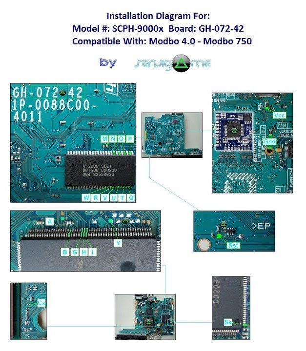
- SCPH-90004 (GH-072-42)
- SCPH-90006 (GH-071-42, GH-072-42)
- SCPH-90007 (GH-071-42)
Note that there are multiple versions of the Modbo modchips available, but the installation diagrams are all the same. Some example versions are Modbo 3.0, Modbo 4.0, Modbo 5.0, and Modbo 750.
For more information about Modbo modchips click here, for more information about PS2 modchips in general click here.
V18 Modbo installation diagram
Installation tips
Here are some tips I have for you when you are soldering your chip into a V18.
- Using 30 AWG solid core wire works well for most of the points.
- Use some thicker wire for the 5V and ground wires.
- Using thinner wire for the (A), B, G, H, and I pins makes things a lot easier. 36 AWG enamel wire along with some flux and slightly pre tinning the pins on the chip seems to work well for me.
- Make sure wherever you are putting your chip won’t cause any issues when putting the system back together, PS2 slims fit together very tightly.
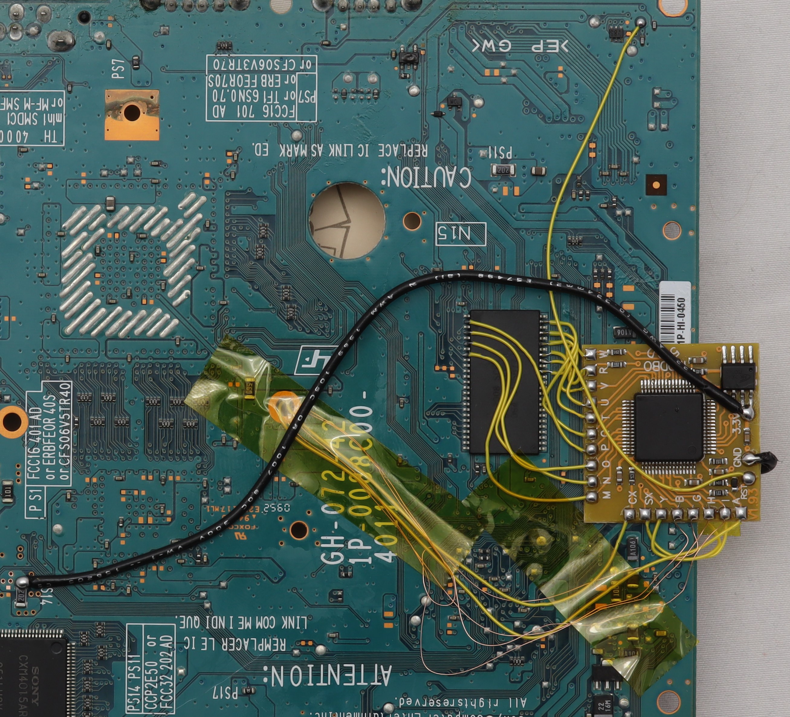
Example installations
This section has photos of some successful installations which you can use to get a better understanding of how everything is wired and positioned. Leave a comment and I’ll add your installation to the list
- William Quade (me)
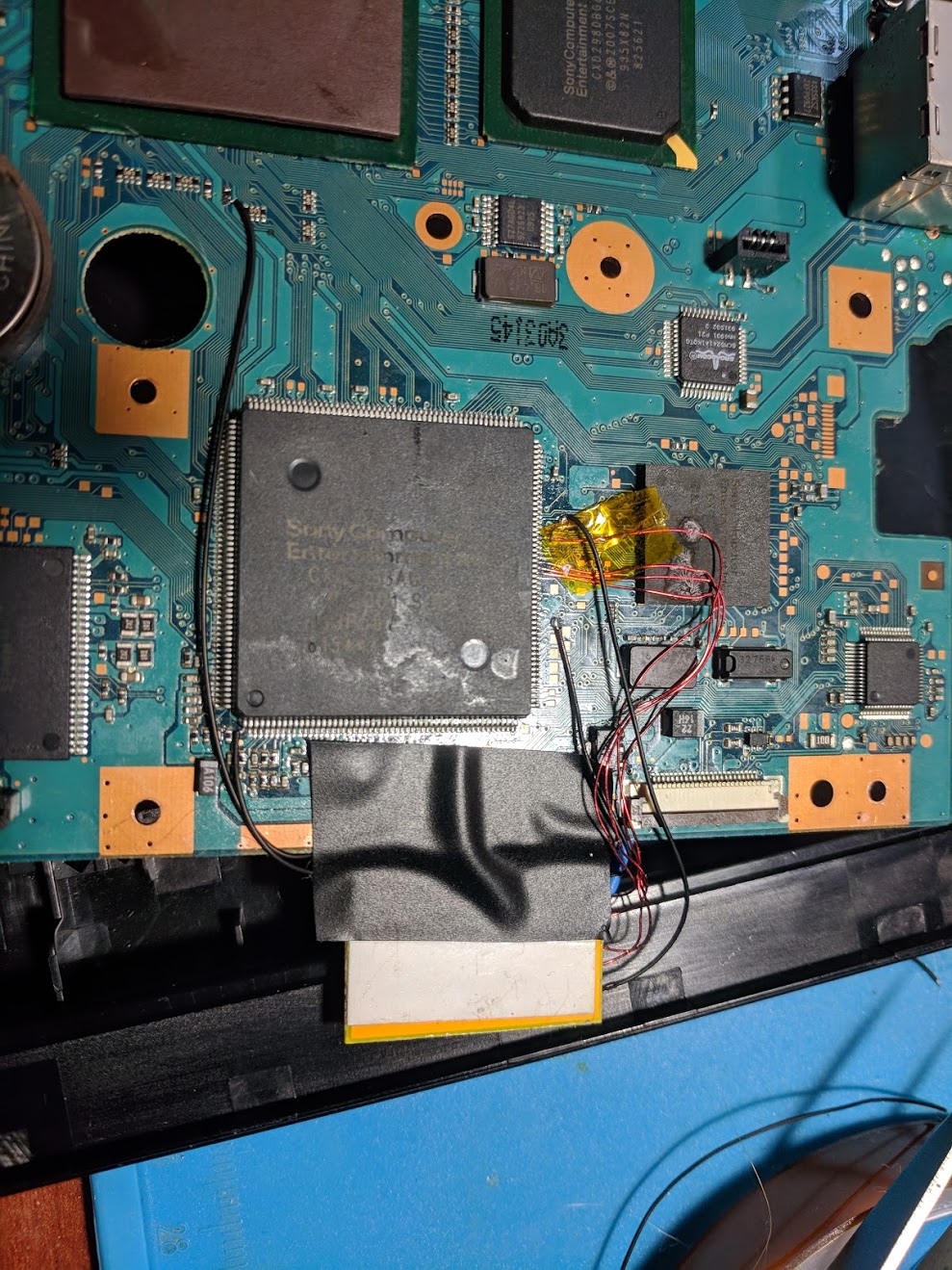
There isn’t much room underneath the board so I found placing the modchip partially off the edge of the underside worked well. Both in terms of having the wires short, and so everything went back together nicely.
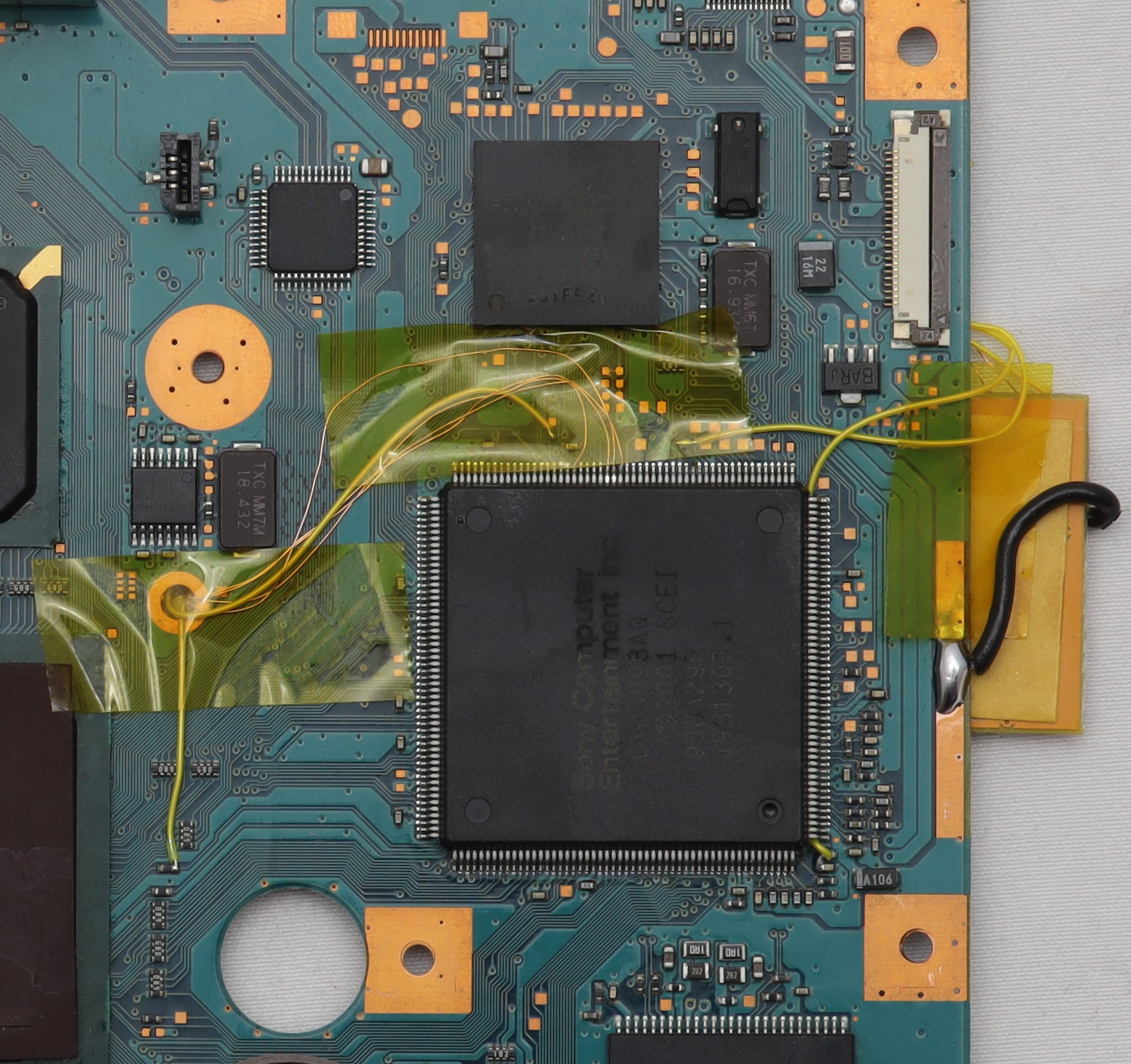
Here is one installation I did. Some of the holes on the board don’t actually have screws that go through them and can be used to route wires through. Keeping the chip further into the board (less overhang) makes it fit into the case a little nicer.
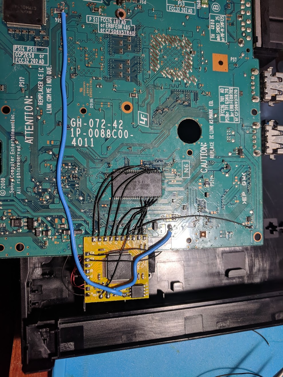
This is an older installation. I didn’t use any of the holes on the board to route wires on this one. I also used thicker wires for the B, G, I, I lines.
Done!
and the back side
Hello
I have the same board
How in the world have you soldered I,H,B,G?
they’re too small
Be careful and take your time. There’s a good chance you’ll mess something up on the first attempt.
Hi William I’m about to take the leap and am going to order a 5.0 soon. Where do you get your 36/30awg wire? I live in a rural area and the smallest I can find is 20.
You can buy it from Amazon or eBay.
i used magnifiying glass 10x and 20x with LED light to see it clearly.
Try Indonesia way. Use 2 peice of thin paper to prevent you stick all IC feet when install the jumper cable. Slide the paper both on left and right feet. i.e. if you work with point H then slide paper between H-G and H-I. and see how easy it will be…
Hey everyone! I am really looking forward to starting this project but I am a little confused about one of the pictures. I have a GH-071-42, so the first set of pictures. I am looking at where the SX wire attaches to the board and it almost seems like you need to bridge the ends of the two components (the blue drawn line seems to cover both). Looking at my motherboard, there are four components in a row, and picture shows the blue line covering the third (yellow) and fourth (black). Could I get some clarification, please and thank you!… Read more »
SCPH 90001 GH-072-42 here. Finally, success but what a pain in the butt! It took me about 2 weeks and multiple failures booting to black screens. I had to remove the Modbo 5. Finally today, I tried to very slowly solder on the bios wires and those impossibly small 4 wires I, H, B, and G. I think the black screens were because of the bios wires lifting the chip legs. I used different points for the ground and 3.3v (I found a random post on reddit with a picture of a recently acquired slim with a modchip installed). I… Read more »
I put one end of the wire at the letters
Where do I put the other
You need to match the letters on the chip to the letters on the board.
I don’t see any letters on the board
Or at least I don’t see them as clearly as the chip
What do you mean?
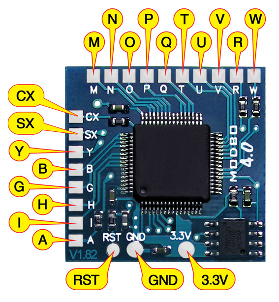
The chip has labeled pads like this:
Match each letter on that chip with the labeled points on the diagram:
Ah I get it
Next question
What is the big blue wire for
Those are the power lines. 3.3V (or VCC) and GND need to be thicker wires because they carry power.
Alright just one more question
The hole that says gnd in it
Do I make the wires touch the floor or just simply hot glue them to the sides
You need to solder the wire to the metal part of the hole. Never use hot glue since it won’t work (at least not reliably).
Okay I think that’s all the knowledge I need
Just gotta wait for the chip to arrive
I have a question how do I stick the wires to the chip without using an air compressor
Do you mean soldering iron? You’ll need a soldering iron, it’s really the only way to attach the wires to the board and chip.
Is there any chance of finding a step by step video on this
How do I solder it without ruining the chip itself from the heat
Pay someone who knows what they are doing.
Can j stick the wires to the chip using duct tape
Moka, don’t take this in a mean way, but your questions are bordering on ridiculous, actually the last one smokes past any border and goes off the deep end. You seriously need to consider taking this job to someone who knows what they’re doing. I’m less worried about your soon to be ruined ps2, and more worried about you burning your house down with a soldering iron. Seriously buddy, take it to a pro.
I successfully installed modbo 5.0 modchip to my PS2 scph-90004 using your guide. Able to run OPL games on my console without the use of FMCB memory card.
Thank you William 🙌
Hey William, great placement on the chip. I’m about to do my 9004 just a quick one. How did you get the metal plate off to expose the top side of the board? Mine seems to be really stuck on. I’ve taken all the screws out (counted 7)
Sometimes it can be pretty hard to remove. You can try twisting it some, and lifting from different spots. It can require a decent amount of force because the thermal pads can stick pretty good sometimes. Heating it up some can help as well.
Never got around to sharing my install with you. Thanks for all your help and guides, Fun mod to do! Just a quick note to all, when disassembling slims make sure you try not to lift the ribbon cable on the laser unit. I lifted mine slightly and ended up scratching some discs as the ribbon was protruding up by a few mm. Easy fix just glue the ribbon cable back down
https://imgur.com/4hYnAfk
https://imgur.com/Wm7f7sY
What gauge wire do you recommend/use for the 5V and ground wires?
Anything in the 20 to 24 AWG range would work well.
hi william, i was wondering if you had higher resolution pictures of the V18 Modbo modchip installation diagrams?
No, these are all that exist at the moment. Zooming in can help.
Higher res for the 072 but a different language. Hope this helps!
Thanks for all this information William. I enjoyed installing modbos on my v7 and v15. I recently i got a cheap v18, but the disc controller wires look impossible to solder. Currently waiting for some 36awg wire and i ll give it a shot i guess. I have zero experience with enamel wire, but it looks like it does not have any insulation around it. Is this true? Or is it my eyes playing tricks on me? Have you by any chance tried to look for alternative wiring points for those? I tried but my multimeter is not great, and… Read more »
There is insulation on the enamel coated wire (the enamel is the insulation). You have to scrape off or burn off the insulation on the ends to more easily solder and get better connections with it.
There are definitely alternate points for at least some of those points on the other side of the board. As you said it’s hard to probe the pins to begin with, so probing a pin while also probing points on the other side of the board isn’t easy.
Oh i see.
Thanks a lot. I ll give finding the alternative points a try at some point. IF i succeed i will post my finding here
Any alt points for the Reset pad? Trying to repair a botched install sent in to me and they ripped the pad clean off.
Based on this higher resolution diagram it looks like the reset line connects to a via right above the point and then to the capacitor above that:
hello everyone, I would like a hand. I should modify a Playstation 2 with motherboard code:
GH-071-42.
The modification chip I should use is “Modbo 5.0”. what scheme do I use? Do I use the same scheme as 4.0?
Thank you all.
Yes. They use the same diagram.
ok perfect, thank you. One last thing that stops me a little is at step number 5 that the SX point has to be welded. Do I have to weld it on both sides? Or just on the “condenser” side?
I’m not exactly sure what you are saying, but the SX point only get soldered to one side of the component (like how it is in the diagram).
Hi, this might be a stupid question but can I use any soldering iron to install the modchip?
A soldering iron is completely necessary. There isn’t any other way to install the chip.
Success!
First Try Modbo 5.0D installation in my PAL SCPH-90004 (GH-072-42) following the Diagram you posted (actually the higher res version i found in the comments here).
Thanks!
Hey
Will this chip work with SCPH-90008? It’s not on your list
Yes.
Thank you
Hello how are you ? I looked a lot for an electrical diagram to change the modchip of my PlayStation 2, which is a scph90006 and I didn’t find it, so I finally had the brilliant idea of searching in English and now I’m here on this wonderful page. I have a question, is it true that the wiring diagrams for installing the modchip are the same? I still can’t believe it. Just excuse the writing, I speak another language, so I had to use a translator
Yes, the diagrams are the same for all regions.
Perfect editing for 72-42 , after testing i noticied that DVD films don’t work in ” AUTO” mode , you have to put “DVD” mode
To be specified for this v18 because it’s the only version that does this
Hi William, with this “modification” it is possible to play original games from Japan having a ps2 pal (European)
Yes. Out of region games will be in black and white if you use composite video though.
I have two questions … the first you know where I can find the chip that controls the laser of a ps2 90001 (gh-72-42). the second, the installation of a chip can make the console laser no longer detect the games, whether they are original or not?
Are you talking about the MECHACON chip? You’d probably have to pull one from another PS2 board. For your second question, yes. A chip that isn’t properly installed can cause a system to not read games at all.
Need help!! I goofed, and I ended up breaking off the one you solder pin I to. I installed the chip the rest of the way (and I scraped away some of the mask and soldered pin I to the trace) but all I get is a blank screen.
I really hope pin I wasn’t some sort of critical pin for the system to boot, because I can’t figure out what else could be wrong; I’ve checked all the other wires and they’re all fine.
I could try and find that chip on Digipart if need be though
You’ll need pin I to connect to both the pin of the chip and the trace. That particular chip is a Sony specific chip so you’d need to get it from a donor PS2 board.
Hello,
I Accidentally ripped that small component and I don’t know the value of it, I presume that is a resistor, so I’ll try to replace with a discrete one if I get to know the value.
My model is the SCPH-90001 GH-072-42.