V17 Modbo modchip installation diagram
The last PlayStation 2 models sold in Japan used the V17 board revision. They were also sold in many PAL markets, but not in North America. Matching console model numbers and board numbers are listed below.
You can find the model number on the sticker on the bottom of the console, and the board number is printed on the PS2 main board if you take apart your console. Note that there can be multiple board numbers within a specific model number.
- NTSC-J (Japan):
- SCPH-90000 CB (GH-070-42)
- PAL
- SCPH-90002 (GH-070-42)
- SCPH-90003 (GH-070-42)
- SCPH-90004 (GH-070-42)
- SCPH-90005 (GH-070-42)
- SCPH-90008 (GH-070-42)
- SCPH-90009 (GH-070-42)
- SCPH-90010 (GH-070-42)
Note that there are multiple versions of the Modbo modchips available, but the installation diagrams are all the same. Some example versions are Modbo 3.0, Modbo 4.0, Modbo 5.0, and Modbo 750.
For more information about Modbo modchips click here, for more information about PS2 modchips in general click here.
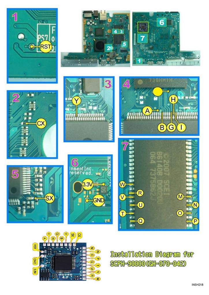
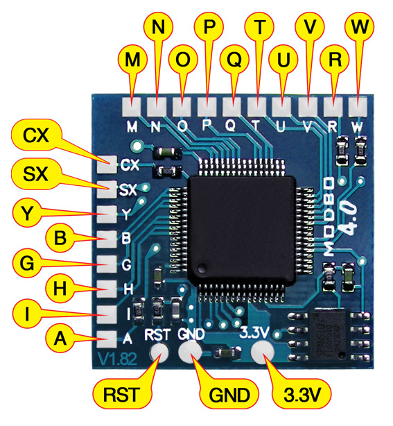
V17 Modbo installation diagram
Installation tips
Here are some tips I have for you when you are soldering your chip into a V17.
- Using 30 AWG solid core wire works well for most of the points.
- Use some thicker wire for the 5V and ground wires.
- Using thinner wire for the (A), B, G, H, and I pins makes things a lot easier. 36 AWG enamel wire along with some flux and slightly pre tinning the pins on the chip seems to work well for me.
- Make sure wherever you are putting your chip won’t cause any issues when putting the system back together, PS2 slims fit together very tightly.
Example installations
This section has photos of some successful installations which you can use to get a better understanding of how everything is wired and positioned. Leave a comment and I’ll add your installation to the list
- Nobody yet
I have got a SPS2 model №90004a PAL. And it has a board GH-070-12.(not GH-070-42). What kind of installations diagram would you recommend?
It’s probably the same diagram.
thanks a lot
Hey, do you know which pin is related to restart modchip after game was booted? Mine won’t restart with PS2, but would do with PSone games.
It shouldn’t restart when playing PS2 games like it does when booting PS1 games. The wires used for PS2 functionality are: A, G, H, I, B
I’ve manage to install my modchip 5.0 using this diagram. Works great!
I installed modbo 5.0 modchip to my PS2 90006(GH-070-042) ,and play ps2 game and DVD well, but can’t boot ps1,I suspect my SX not welded right, but form the guide I am not sure which components to weld, the yellow components or the black components.
Either or both is fine. They are connected through a trace on the board.
Thanks for wonderful work. I use this Diagram for ps2 v17. But after soldering modbo v4 the ps2 doesnt Turn on. The red light glowing. After press the Button,Turn to green. But The screen just black. Where i doing wrong?
You messed something up. Check for blown fuses, and make sure that all of the BIOS pins (M,N,O,P,Q,T,U,V,R,W) are good and not shorted out or anything.
Hello! I have a PS2 slim SCPH-90006 NTSC-J that uses the board GH-070-42 and is preinstalled with a Super 7 E-17 modchip but the SX and Y points are not connected to the motherboard. While trying to solder them on, I accidentally bridged the legs of the chip where Y is located. Would this kill the whole motherboard if plugged in? Thank you.
I’m not sure, but that’s probably not something you’d want to test out. It may be fine, might be fine but not read discs, it may blow a fuse, or it may completely destroy the system.
Thank you for the reply! Just an update, I let someone repair my PS2 yesterday at a local store and fortunately enough, it booted normally. However, it still won’t boot PSX backups. I’m planning to replace the Super 7 E-17 with a Modbo 5.0 and hopefully it’ll be able to boot PS1 games.