V15 Modbo modchip installation diagram
One of the revisions of the slim PlayStation 2 was the V15. They were found in SCPH-7700x models available worldwide. Matching console model numbers and board numbers are listed below.
You can find the model number on the sticker on the bottom of the console, and the board number is printed on the PS2 main board if you take apart your console. Note that there can be multiple board numbers within a specific model number.
- NTSC-J (Japan):
- SCPH-77000 (GH-052-12)
- NTSC-U/C (USA)
- SCPH-77001 CB (GH-051-02, GH-051-51)
- PAL
- SCPH-77002 (GH-051-02)
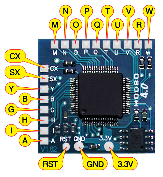
Note that there are multiple versions of the Modbo modchips available, but the installation diagrams are all the same. Some example versions are Modbo 3.0, Modbo 4.0, Modbo 5.0, and Modbo 750.
For more information about Modbo modchips click here, for more information about PS2 modchips in general click here.
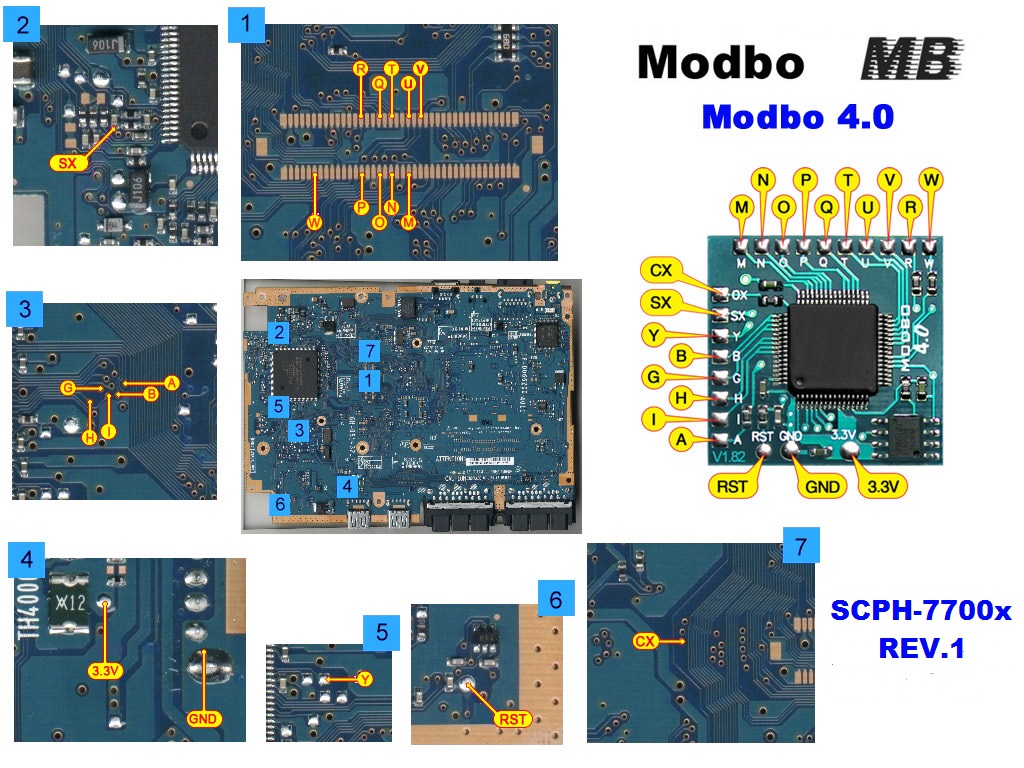
V15 Modbo installation diagram
Installation tips
Here are some tips I have for you when you are soldering your chip into a V15.
- Using 30 AWG solid core wire works well for most of the points.
- Use some thicker wire for the 5V and ground wires.
- Make sure wherever you are putting your chip won’t cause any issues when putting the system back together, PS2 slims fit together very tightly.
Example installations
This section has photos of some successful installations which you can use to get a better understanding of how everything is wired and positioned. Leave a comment and I’ll add your installation to the list
- William Quade (me)
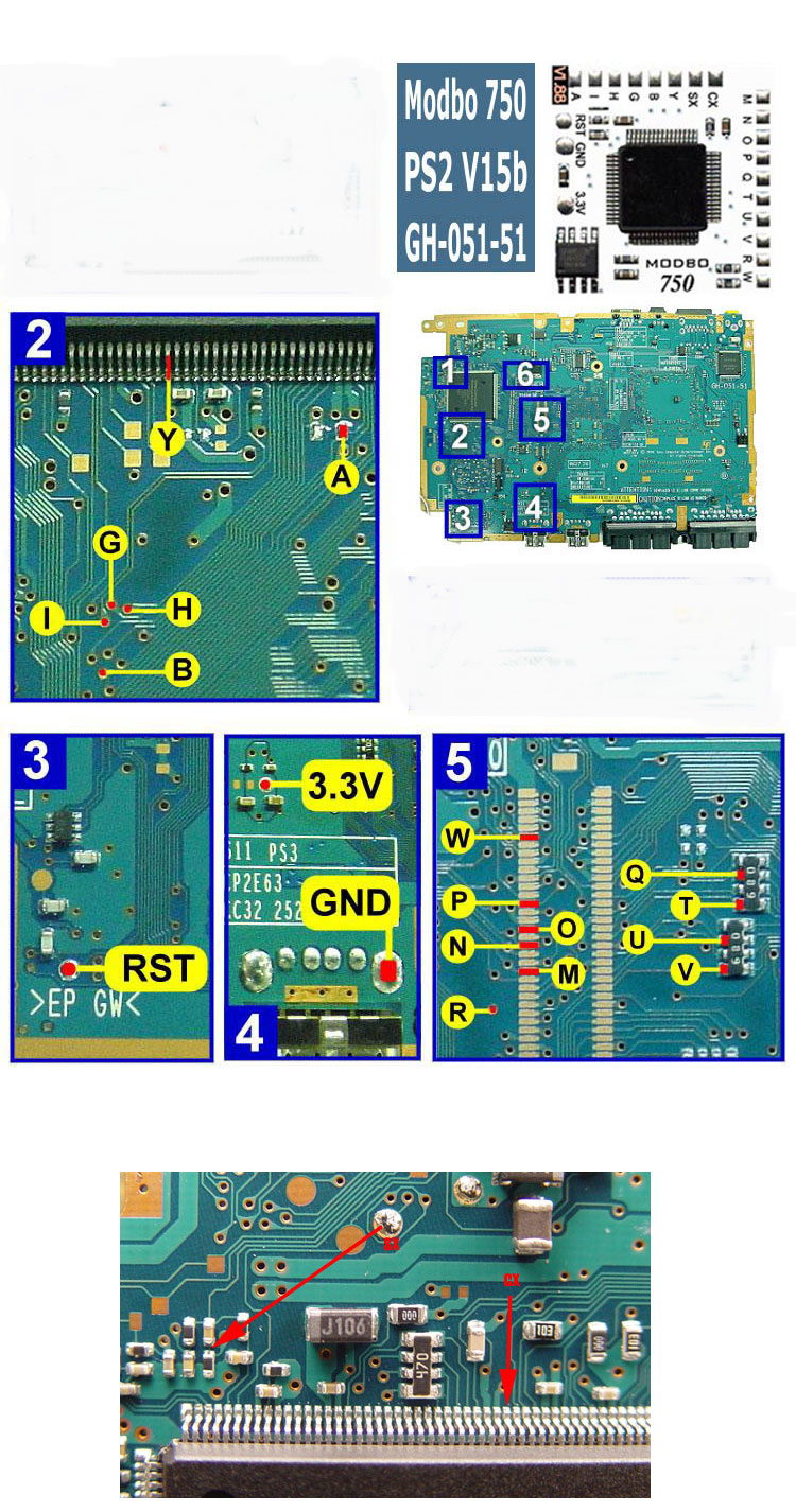
This board matches the second diagram with the Modbo 750 chip. I found some alternative points for some of the connections (like Q, T, U, V, and R).

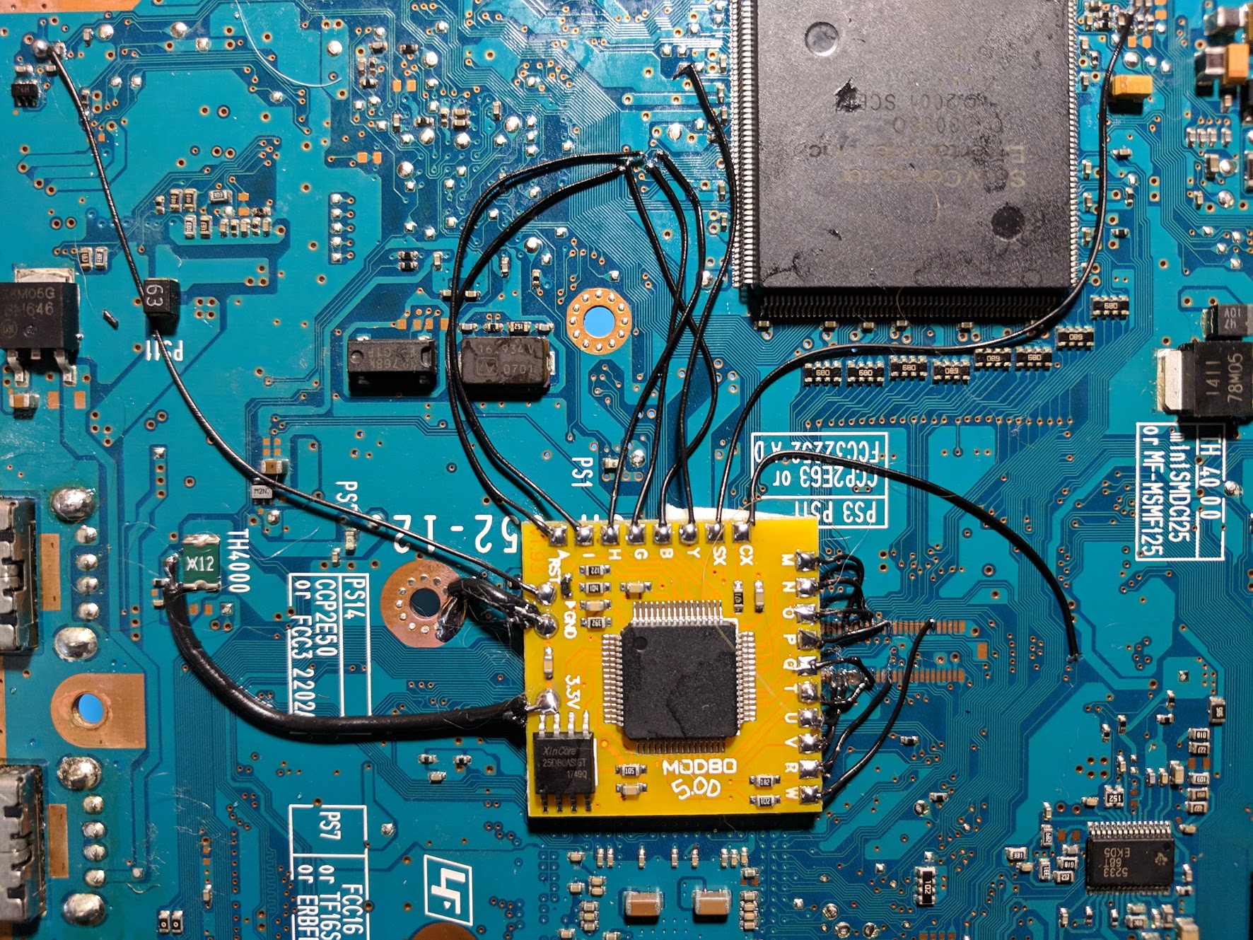
This is an example of an installation into the first diagram with the Modbo 4.0 chip. It shows that there are multiple valid places you can position the chip and have a working install. I tend to prefer the position in the other example.
GH-051-51 has different layout then whats posted, please fix this.
I’ve installed Modbo 5 using these installation instructions on a PAL SCPH-77003 (GH-051-32). Confirmed as working! Thanks
I’ve installed Modbo 5 using these installation instructions on a PAL SCPH-77004.
It boots up with the maitrix logo, then it says loading boot menu.
Then I get Unable to load config file.
What could be wrong here?
Boot into the config menu by holding triangle and circle at boot. Then set boot mode to auto.
I just installed on a slim the GH-051-32 and i bought 2 chips 1 for the slim and the other for a friends im fixing but i tried both chips on the slime and i keep getting failed to load config file with 4 red ! ! ! ! iv read that this is means bad flash on these chips so Whats wrong i Have triple checked my wiring
Set boot mode to auto in the config menu (access config menu by pressing and holding triangle and circle at boot).
so the console boots now but it keeps giving me the red screen of death when playing disks i put a new laser and data cable before instaling the chip
Could be an issue with one of the A, B, G, H, I wires.
even if the disk is the original disk not a custom disk
Yes. You can try disabling the chip by pressing and holding start at boot.
Successful install using these instructions on a silver NTSC/U GH-51-01. Important note: My unit has thick lacquer on the circuit board that couldn’t be removed from the vias with a fiberglass scratch brush without ALSO removing lacquer from nearby ground flood adjacent traces. In order to expose these vias so they could be properly soldered to I needed to carefully scrape them with the tip of a thin needle file. A fine hobby knife could also do the trick–just be careful.
I have a SCPH 77004b, what guide should i use, because none of them are matching my board ( GH-052-51 )
Follow the V15 diagrams.
The boards don’t match, i can send you pictures via e-mail if you want
Yeah send me some pictures in an email, or link to them in a comment.
I’m having a problem with the modbo 750 models. They don’t seem to read the psx CDs but PS2 DVDs work.
You’ll want to check to make sure the SX point is correct and has a good connection, since that’s the line that’s used for PS1 backups. It could also be the laser being worn since the CD and DVD parts wear separately.
Looking for the GH-051-51 diagram, the current one above is different than mine
If you send some photos of your board that would help. You might just not be looking at the correct part of the board or something.
sent sir
I added another diagram to this page that matches your pictures. You may want to probe around with a multimeter to find alternate points for some of them in that second diagram.

i have a gh-052-02 that doesnt match any of the diagrams
It’s likely one of the two on this page, the name itself doesn’t have to be an exact match. Just compare points on the board to find the closest match.
hi! i have an SCPH-77000 japanese slim ps2 and a modbo 5.0 chip. will these diagrams with the 4.0 chip work even though i have a different chip??? do any modifications need to be made to the 5.0 chip?? very nervous about messing up my board 🙁
Read the actual post. I mention it works with 4.0 and 5.0 and other Modbo versions.
I’ve got a GH-052-12 but it’s ntsc not Japanese is it still the same as the 1st diagram? Also the 2 rows of solder pads for w, p, o, n, m, etc have a couple pads that seem to be connected to through holes right next to them, I should be able to use that through hole as an alternate point correct? Thanks for the diagrams by the way. I installed multiple chips thanks to your work most recently an mm3 and an attiny 85.
Use whatever diagram matches your board regardless of region (whatever GH-## is closest, and then just by comparing the diagram to the board). You can use anything that is connected to those same points, including those via holes.
Awesome thanks man. Little sidenote I found a bubble mailer today with your name on it lol I didn’t know I’ve gotten any chips from you but I buy quite a bit of different chips from ebay so it makes sense. I’m assuming it was either this modbo, the mm3, the attiny 85, or some kynar wire wrap. Those are my most recent purchases so probably one of those but it was cool to see your name on there and to find out I’ve bought something from you lol. Thanks for all the diagrams and tips man keep up the… Read more »
Thank you for your great guides! I just installed a Modbo 5.0 on a GH-051-12 which is not listed here (is it missing?). I apologize for the messy cable management, this was my first job on a PS2 😉 But everything works fine!
If you like I can provide a photo of the board with the chip installed (the image upload here always says unsupported file type).
Can I also trace the via connections B, G, A, I, H up to the big chip and solder the cables to the chip’s legs? Guess it would be easier that way than soldering it into/on the vias…
Yes
Great – thank you!
I’ve successfully mod-chipped my SCHP-77002. Sometimes it has issues booting games, but I believe that has something to do with the back disc drive button not being properly depressed. It usually boots up if I apply pressure to the back of the ps2 disc lid, where the switch is located. I chose to solder into the vias, as they were exposed, and the tip + solder wire I was using was too large for the job.
edit. website not allowing me to upload JPEG picture. It says format not allowed?
You can upload to another website like Imgur and post a link if you want. You could try jamming the little switch closed with something.
hello what diagram to use for model scph 77004 pal? thank you
Probably one of these. Read the page, look at the diagrams, find the one that matches your board the most.
Ok thanks you
Hello there! 77001 PS2 with GH-051-02 board. Install went well. Nothing bridged crossed up, that I can see. Plugged it in to test and it powers on, but the fan is going full blast, and I get no video whatsoever. This was/is a working unit. Not my first rodeo modding wise, but it is my first ModBo. Any one else encounter this? I going to tear it back down and go over it with my 10x monocle again, but I’m trying to get some insight in case I’m missing something. Maybe i got a bad Modbo? Any possible info/help would… Read more »
So I’ve successfully installed a chip in two slim black 70001 ps2’s but I recently installed a chip in a 77001 and it booted up like it should and I saw the matrix thing like usual but for some reason I can’t play any discs. The ps2 was working before I attempted to install the chip and after the install I can’t even play regular ps2 discs… Any thoughts on what might have gone wrong? I did take it apart and change the laser and I still get the same error “please put in a PlayStation formatted disc”
Check the A, B, G, H, I pins since they are what is needed for running games. Chinese replacement lasers can also just be bad.
I noticed someone else had the same issue just before me so I’ll be checking those connectors. The laser came out of a ps2 that had a great laser. I was working on a silver ps2 and I took it from a black one just because I like the silver. Thank you for the reply!
Just thought you’d like to know it was the I pin! Thank you so much, do you have like a list of what each pin does in case I encounter any other silly issues? Thanks again, you are a legend
SX – For PS1 backups.
CX – Clock line for timing.
3.3V, GND – For power.
Y – For DVD playback.
A, G, H, I, B – For PS2 backups.
M, N, O, P, Q, T, U, V, R, W – For BIOS patching (what causes the Matrix boot screen and configuration menu to work).
RST – To detect reset button presses.
I have an NTSC 77001 with board GH-052-51. The board via locations dont seem to line up with the pics for the V15. Is there a different version I should be looking at? I’m installing the modbo 5.0
I just attempted this install and I believe the chip is working, but when I try and play a back up I just get a disk read error. Official ps2 game work fine but none of my back ups work. Any help would be appreciated cheers.
Where i find diagram of modbo 5 for SCPH 77004 ? Please help
Looks like you found the right page.
Hi, Gang!
77001 PS2 with GH-051-02 board.
Just finished install. Double checked wiring, and reassembled. Disc spins up. Laser moves like its reading. Fan works…..No video! Composite OR component. Anyone else had this happen? Could it be the chip? Not sure where to go here. This is/was a functioning unit right before I installed this chip. Going to tear it down AGAIN(third time), but if anyone has encountered this, any help would great.
Thanks
Update:
Ran some more tests. same result no matter what I did. Tore everything down after checking wiring positions and continuity. Something didn’t seem right with the ground and power on the chip. Thinking I got a bad Modbo. Yanked it out and the unit works perfectly
! Going to order another chip or two and give that a shot. In the mean time I’ll check my wires again. Still want to hear if anyone else has encountered this.
Thanks
Update:
New chips arrived, and installed one. Didn’t undo any wiring from the previous chip removal, just soldered the new one in. Unit functions great! so it came down to a bad chip being the cause of all of my problems. Hope this helps someone with the issue down the road if it happens.
It’s works, thanks !