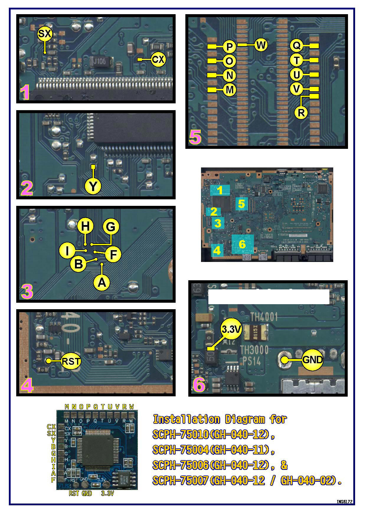
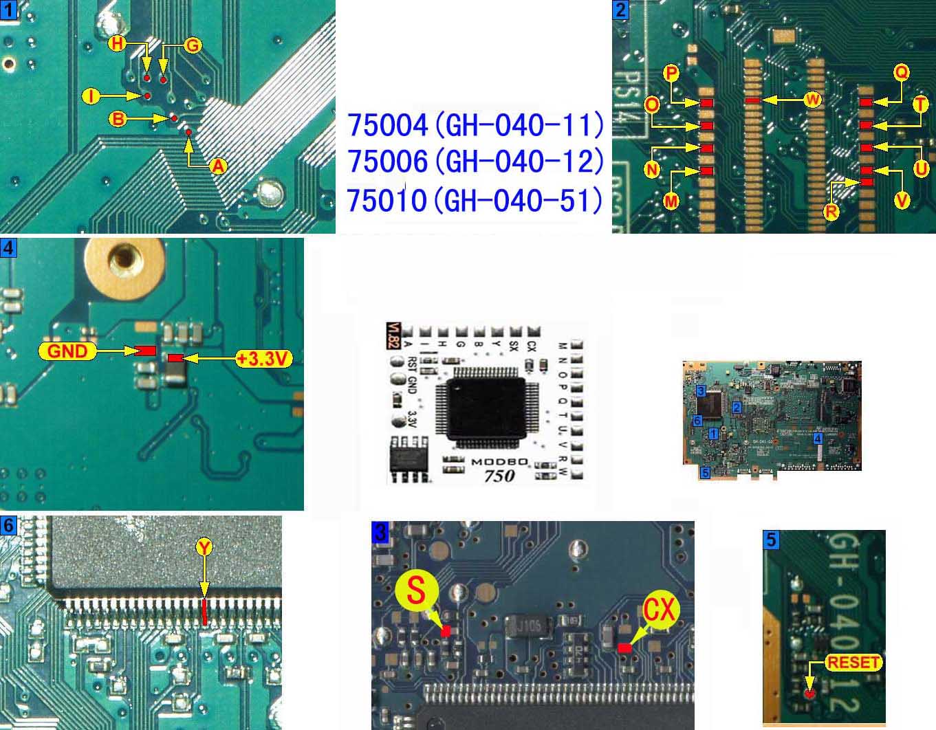
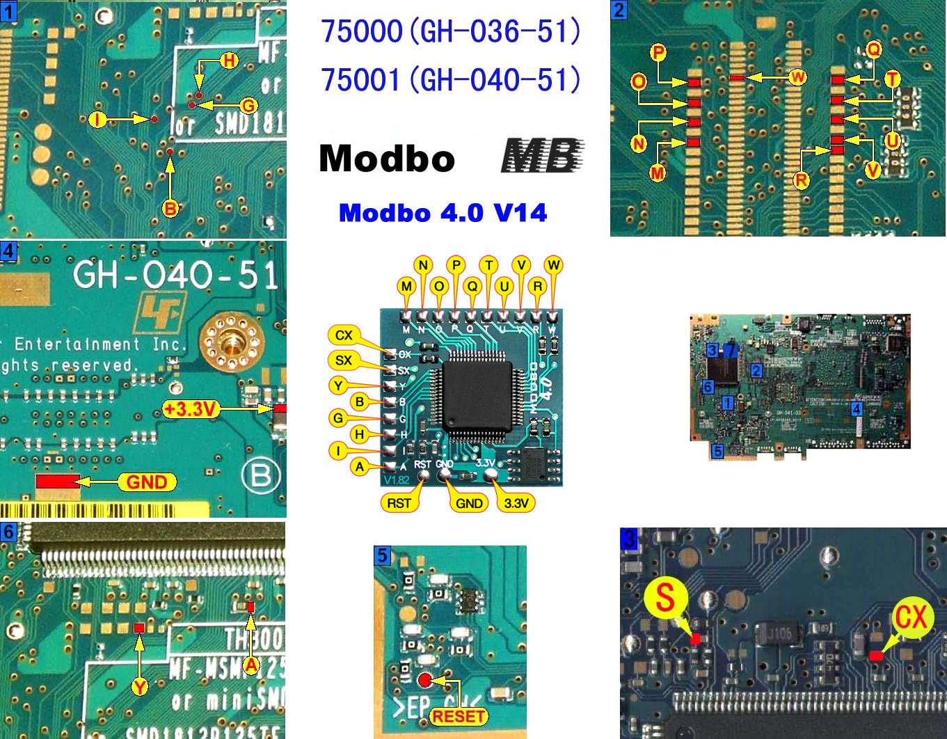
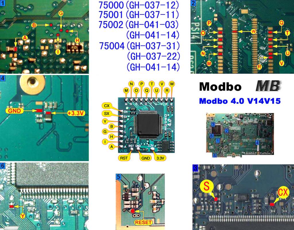
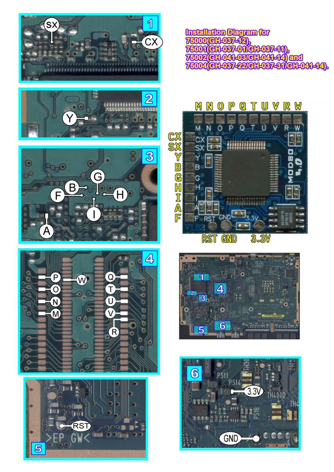
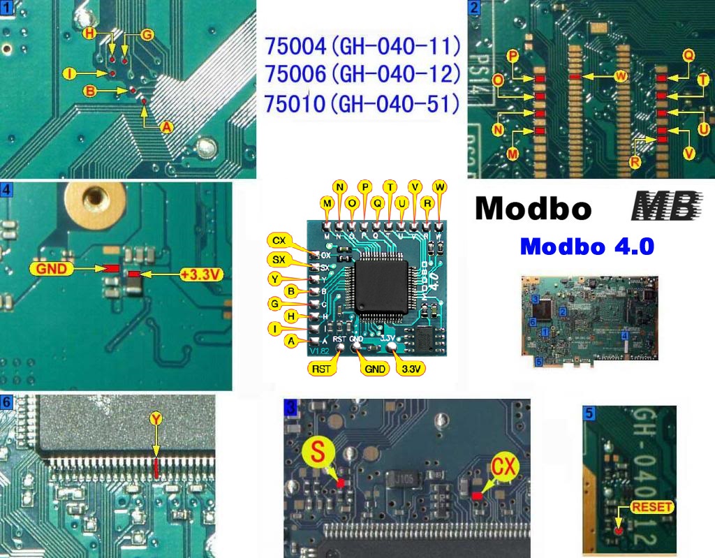
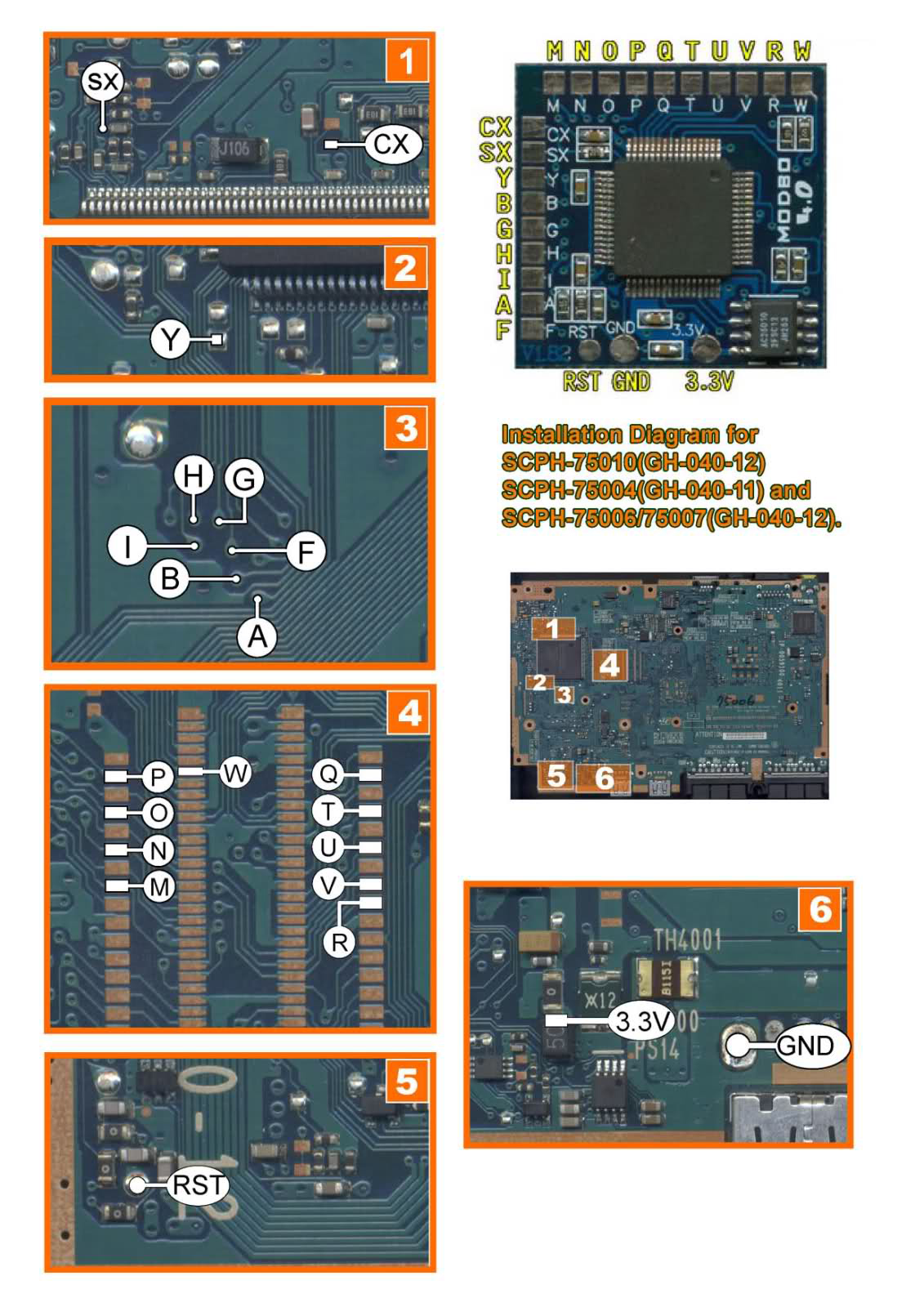
V14 Modbo modchip installation diagram
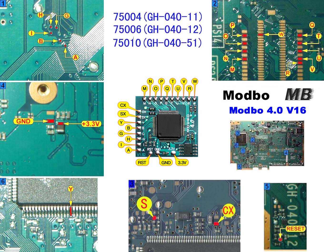
One of the revisions of the slim PlayStation 2 was the V14. They were found in SCPH-7500x models available worldwide. These were the very first version of the PS2 slims that had a reduced number of compatible PS1 and PS2 games. Matching console model numbers and board numbers are listed below.
You can find the model number on the sticker on the bottom of the console, and the board number is printed on the PS2 main board if you take apart your console. Note that there can be multiple board numbers within a specific model number.
- NTSC-J (Japan):
- SCPH-75000 CW (GH-036-51)
- SCPH-75000 SS (GH-037-12)
- NTSC-U/C (USA)
- SCPH-75001 (GH-032-32, GH-036-51, GH-037-01, GH-040-51)
- PAL
- SCPH-75002 (GH-041-14)
- SCPH-75002A (GH-041-14)
- SCPH-75003 (GH-041-14)
- SCPH-75004 (GH-040-12, GH-041-04, GH-041-14)
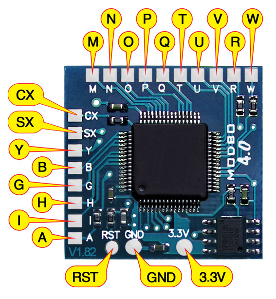
Note that there are multiple versions of the Modbo modchips available, but the installation diagrams are all the same. Some example versions are Modbo 3.0, Modbo 4.0, Modbo 5.0, and Modbo 750.
For more information about Modbo modchips click here, for more information about PS2 modchips in general click here.
V14 Modbo installation diagram
There are a lot of diagrams out there for this model. I’ve included all of the diagrams I have, but will likely be removing the ones that appear to be duplicates in the future.

Installation tips
Here are some tips I have for you when you are soldering your chip into a V14.
- Using 30 AWG solid core wire works well for most of the points.
- Use some thicker wire for the 5V and ground wires.
- Make sure wherever you are putting your chip won’t cause any issues when putting the system back together, PS2 slims fit together very tightly.
Example installations
This section has photos of some successful installations which you can use to get a better understanding of how everything is wired and positioned. Leave a comment and I’ll add your installation to the list
- Nobody yet
Hey just wanted you to know I used these diagrams on my GH-040-52 even tho it isn’t listed anywhere. It worked perfectly! Thanks!
thanks for tghe photo, i have the same model of motherboard and works great.
Any advice on soldering these? I can’t get them to solder, sorry still a noob 🙁
You may need to scratch away the solder mask on the vias themselves if there is solder mask on top of them.
Yo tengo una slim SCPH-75001 GH-040-52 pero no aparece ese diagrama
Maybe this one?
no mano es GH-040-52 pero tu crees que sirva esa?
Yes, it is probably the right diagram. You need to match your board by comparing your board to the diagram, not by finding an exact board number match.
Bueno mano voy a probar con ese a ver
Hello,
I have installed a Modbo 5.0D chip. I have a 75001/GH-040-12 motherboard.
I used a combination of 2 different diagrams. My problem is, after installing it, there is no video output, I just get a black screen.
The PS2 seems to boot the system and spin the disc and then stop.
I have validated the connections and there appear to be no shorts. Is there anything else I should or can check?
Thank you in advance.
Make sure you didn’t blow any fuses on the PS2 board. Also try to get into the config menu (pressing and holding triangle and circle at boot).
I was unable to get into the config menu. Maybe I did (but I couldn’t see it). I tried removing power from the chip to see if the system would boot, but no success. I believe there is some form of video output, as my TV goes from saying “No Signal” to a black screen. I checked the fuses that I could tell were fuses and they seem okay. Do you know the designation of any other fuses I should check? For the GH-040-12 board, I noticed there weren’t any diagrams that matched the CX pin location, so I chose… Read more »
A quick addendum to my last post.
I did a further test where I removed every wire from the Modbo and the system booted and had output. I am going to add every wire 1-by-1 and see if I can find the problem.
Another quick addendum, I’ve isolated the problem to the “T” connection. Whenever, I connect this wire, I get no video output.
I finally got it working. Turns out, I had the “W” wire connected to the wrong pin. Such a silly mistake. Thanks for the assistance.
Just installed a Modbo 5.0 in a white japanese scph-75000 using these instructions.
Works perfectly, no problems.
My ps2 slim is a pal scph-75003 but it says on the board that its a GH-037-01. Wondering which diagram i should use? Thanks.
One of these diagrams should work. Just find the points on your board using the diagrams, if you can’t find a point try another diagram.
Thanks. Was able to find a diagram for GH-037-02 which i was able to use and everything works fine. Only problem is G,H,I,B im struggling to solder onto those points (im new to soldering) but everything else is fine. Do you know any tips for soldering onto those points or perhaps id be able to solder onto the chip instead? I wanted to use it to play imports but that’s the only thing that i can’t get working lol.
For those points I carefully scrape off the soldermask from the vias along with slightly drilling them out a bit (I use an xacto knife for both). The alternative is to solder to the pins on the chip like in the V18 board diagrams (the chip is the same and so are those points), but soldering to those legs isn’t really any easier.
Hi, i did what you said about drilling out the vias and now everything works perfectly.
yo tengo una ps2 scph-75001 modelo de placa gh-040-52 y no consigo el diagrama, agradezco de ante mano la ayuda
Hello!
I’m 90 percent done with modding a GH-40-02 with a modbo 5.0 when I realized the only diagram with it has the modbo 4.0! Should I use a different diagram, or do I need a 4.0?
Many thanks, love your website, your resources are incredibly useful.
To be more specific, the diagram includes an F point, which I’m missing.
No need to connect the F point if there isn’t one on your chip.
I have a question: You can solder on a PS2 7500x GH-040-12 pin Y at the point of version 7600x HG-040-12. In the original matrixes it has to be welded at that point and it seems easier to me. Does it serve as an alternative point? My PS2 has that alternate Y point and since the original matrix is soldered there I’m not sure what to do. I think it would be the same. I have a slimline PS2 SCPH 75004 with board GH-040-12 And one more doubt: to solder pins H, G, I, B, A, do you have to… Read more »
If the two Y points are connected to each other (you can use a multimeter to test) then either point can be used.
Yes, you’ll need to carefully scratch any solder mask off of the H, G, I, B, A points to make a good connection.
Thank you so much.
I have tried it but now it cuts with dough (visibly it gives the feeling that it is fine). What can I do about it, I turn it on to see what happens. I think the mass ground is right next to it.
If I scratch a little more than I should what would happen? Would I stay without the possibility of putting a chip or would I run out of a console?
Thanks for the advice but I cannot scratch those pins, it is impossible for me and I have tried to solder the legs of the integrated but it is even more difficult since the tin does not grip the soldering iron tip and then put it in place. I don’t know what I can do with those pins, with the rest I have no problem. By the way, try scraping them off with a 1.4mm flat-blade screwdriver. Could you advise me on what to use for scratching?. I have seen a video where they use a sandpaper that rotates. And… Read more »
If you’re trying to solder to the pins on the chip itself then you’ll definitely need to use extra flux otherwise solder won’t easily stick to the pins. You only need an extremely small amount of extra solder though, too much will just bridge across the pins. I use 36 AWG enamel coated wire (that has the ends tinned with solder and then trimmed) for these pins since it’s much easier to solder than regular 30 AWG wire. If you’re trying to solder to those vias then you will need to scrape off any solder mask that may be on… Read more »
I installed a modbo 5.0 onto a V14 ps2. My issue is with backup PS2 DVD games will only work on first boot of the console (have disc inside and power console on). If I go into the ps2 browser I get the red screen “Please insert a Playstation 2 format disc” all other disc formats work with no issue. I have re-soldered points A, B, G, H, & I. I have even re-worked every point multiple of times. Is this a bad chip? or any ideas?
That’s kind of weird. Is it just PS2 DVD games? What about PS1 games and PS2 CD games?
PS1 backup/original work fine as well as PS2 CD backup/original. PS2 DVD originals work fine. It’s only happening with PS2 DVD backups. I’m stumped. I’ve installed a new lens, same issue. I’ve also used multimeter and tested continuity on each point.
Interesting. I’m not quite sure what the issue would be if the other types of media work and you tried another laser. Does it happen if you disable the chip (by holding the start button when booting)?
No issues when disabling the chip. Obviously only originals only work at that point. I have a new chip coming in, I’m hoping it solves the issue.
Hey, I am having this same issue where everything works except PS2 Backups. Were you able to solve the problem? I’ve even checked continuity by finding the leg on the CD DVD drive chip and then touching the point on the modbo and the multimeter beeps.
Hey I ended up fixing mine by redoing the G, H, B, I, A, and Y connections. I also had Y ran under the legs of the big main chip and I took it out from under there as well. I now have it just running the same direction but not under the legs. Maybe that had something to do with it? I also took alcohol and cleaned my laser as well as cover every point on the chip and motherboard that connected to the chip with kynar tape to stop it from touching the metal by any chance.
I have not fixed my issue. I got a new chip and removed all previous wires and soldered new wires. I’m still having the same issue. But again the DVD backup works only when I boot the console up the first time. If I boot up the console without a disc and go into the PS2 browser, insert my DVD game backup it will detect the disc. But if I then open the lid and switch to another DVD game backup or keep the same backup disc I get the PS2 red screen. Is this normal? I don’t have this… Read more »
Hey I ended up replacing the laser and the ribbon cable in this one to get it to work. You may want to look into that. I thought I had it but it kept giving me errors. New laser works tho. Your laser is probably giving out. They’re fairly cheap on Amazon. Easy to replace too. I use DVD+R but people say it can be different for every system.
My issue was fixed. I switched to using DVD+R and changed the booktype to DVD-ROM before burning onto a DVD. Disc works fine every time now.
hi guys i’m know to this i seem can’t find diagram for GH-040-02
One of the diagrams on this page will work. Just compare your actual board layout to find a matching diagram.
yeh thanks man i just find ‘it
Hello br, my ps GH-040-52 but name ScPh 75000
What map man?
One of the diagrams on this page will work. Just compare your actual board layout to find a matching diagram.
Thank bro, hey i find your fb
Hello will the Modbo v1.2 plus work in my ps2 75001?
Probably. I’m not familiar with that particular version.
ok. why is my ps2 75001 fan running when in standby mode (red light) is that normal?
No. It shouldn’t behave any differently from before you installed the chip.
Can someone please help me identify the value of the surface mount resistor that point S connects to?
SCHP-75001 using the GH-040-51 diagram here:
I accidentally lifted the resistor off the board and lost it and do not know what to replace it with. I was able to connect wires to either side of where it went so I can easily float in a new resistor.
Hello!
I really appreciate your work. I often use your guides. I have a question about modbo 4.0 mounted on the V14 motherboard. Do I have to mount a “laser fix” for this?
If it’s a V14 then you don’t need the laser fix, that’s just for the V12.
Thank you very much for your help 🙂
Im struggling with threading wire through the through holes any tips ? It had some stuff covering them and dunno how to remove it from the holes i used scratch pen but no luck so far
Use a small knife to scratch away the solder mask. The wire also needs to be super thin, 30 AWG doesn’t always even thread through them.
I successfully got it working. I need to work on cleaning up the wiring but overall not too bad
Modbo V1.39 to V5.0?
Hi Quade i recently aqquired a Ps2 Scph 75000 with motherboard G40-14 it has a really old Modbo V1.39 modchip and some weird little flex board soldered near the reset location can n simply swap the Modchip to a V5 one simple by soldering over the wires as i don’t have the skills to solder the mother board those connecting points are way to small?
You can’t have two modchips installed into the same system. The old chip may also not use the CX point while the new chip will.
Posso usar esse mesmo esquema nesse modelo GH 032-64?
Yes.
Best diagram to use for gh 41-04 please and thank you
You’ll need to look at your particular board. If you can’t find a point that matches in the diagram try another diagram until you find the point.
Thank you
I have the GH-40-52 and using the genuine Matrix Infinity. the diagram for GH-40-51 should work for this but what is #7? I looked at other diagrams and there seems to be a “Z” in the #7 area. The Matrix Infinity board or other boards don’t have a “Z”?
Z was only on some of the older versions of these chips. Just ignore it.
I have 75001 slim, motherboard GH-037-11. I have installed modbo 5.0 long time ago and it works great. Now recently, I have some weird quirks. If I insert a back up DVD-R or DVD+R game, I will see the Matrix boot logo but then later the red screen. PS1 official/backups and PS2 official games work fine. Sometimes the PS2 will turn on and its just a black screen and I have to reboot a few times before I get the matrix logo and boot into the OS. Not sure how to troubleshoot this. All connections look fine. I’ve ready possibly… Read more »
Quick update: I fixed it. I had a few loose or weak solder connections for some of the wires to the modchip itself. Once I fixed those, modchip works perfectly. Posted in case helps anyone in the future!
hi, i got some matrix infinity V1.93 II chips. Can i use these diagrams to make it work?
Yes