V13 Modbo modchip installation diagram
One of the revisions of the slim PlayStation 2 was the V13. They were found in some of the SCPH-7000x models available worldwide. The V13 is a slightly improved version of the V12 which fixed the laser issues with the V12, while still retaining the full PS1 backwards compatibility lacking in later models. Matching console model numbers and board numbers are listed below.
You can find the model number on the sticker on the bottom of the console, and the board number is printed on the PS2 main board if you take apart your console. Note that there can be multiple board numbers within a specific model number.
- NTSC-J (Japan):
- SCPH-70000 CB (GH-037-01)
- NTSC-U/C (USA)
- SCPH-70001 CB (GH-032-13)
- PAL
- SCPH-70004 (GH-032-12, GH-032-13)
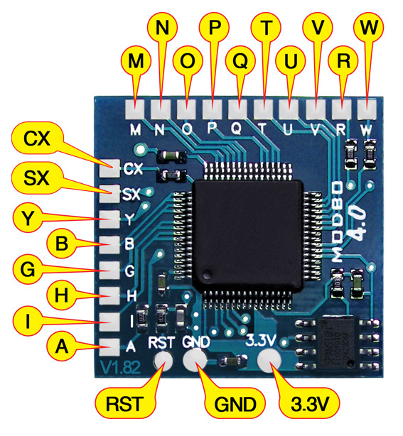
Note that there are multiple versions of the Modbo modchips available, but the installation diagrams are all the same. Some example versions are Modbo 3.0, Modbo 4.0, Modbo 5.0, and Modbo 750.
For more information about Modbo modchips click here, for more information about PS2 modchips in general click here.
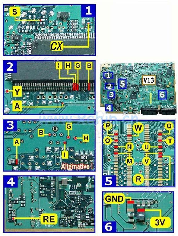
V13 Modbo installation diagram
Installation tips
Here are some tips I have for you when you are soldering your chip into a V13.
- Using 30 AWG solid core wire works well for most of the points.
- Use some thicker wire for the 5V and ground wires.
- Make sure wherever you are putting your chip won’t cause any issues when putting the system back together, PS2 slims fit together very tightly.
- The alternative A, B, G, H, I points are much easier to solder to than the points directly on the chip. Just stuck a longer 30 AWG wire through the via and apply a little bit of solder.
Example installations
This section has photos of some successful installations which you can use to get a better understanding of how everything is wired and positioned. Leave a comment and I’ll add your installation to the list
- William Quade (me)

This is an awesome site for finding diagrams dude, thanks a lot.
Should I follow this guide for an SCPH-70004 GH-032-11?
Thanks
Yes.
And it works!
Thanks so much man
Good for SCPH-70004 GH-032-54 ??
Probably.
my ps2 set to boot in Mass mode , unable to load config file !!!!
i have to fi what ?
Thanks for this William. Did my first Modbo install using this guide and it worked perfectly!
Hello,
Is it good diagram for GH-032-31 board ?
It’s SCPH-70004 model.
Yes.
I should have asked also is it V13 ? Or is it v12 and I should make a laser fix
It should be a V13, which is safe
Thank you for all your tutorials, they are really super detailed perfectly.
However I would have a question, I have an original console never fitted with a chip and whose player does not turn, does not move, really no reaction even with a new one. All the fuses are good, the cable has been changed and the connectors cleaned. An idea of the problem ? If not I would still like to mount a chip on it to use the console only in USB mode, to avoid having to solder everything, which are essential for operation in USB?
Thank you
Make sure you have removed the anti static / ESD protection solder blob on the laser assembly if you bought a new laser. For just USB operation I’d imagine you’d need these pins at a minimum: M, N, O, P, Q, T, U, V, R, W, CX, Reset, 3.3V, GND.
yes I have removed the anti static protection, the reader works very well on another ps2 but on the v13 we can feel the translation motor rumble, and by slightly lifting the pinion of the lens bar, the axis turns. .
The optics are good because it works very well on another slim ps2 . I really don’t see where this could come from
I even tried to change the travel motor and always the same problem
Hello guys I have the same troubble on a v15, I have triple check my connection but still have the same issue than you. I have try to revert connection which control DVD player (GHIBA connection) but still the same problem, the disc won’t spin. I tried to disable the modchip (remove 3v3 and gnd wire) the same thing occure. If you have any suggestions to fix this problem. Obviously, both switch to detect console openning are close.
look at the fuses PSx 1-2-3-4-5 … all
I have already checked those indicated here
But I still have the same problem?
Was your problem with a fuse? can you tell me which one?
Thank you for your help !
your problem has nothing to do with the chip because me there is no chip and the dvd turns except that the motor of the lens rumbles and does not move when I put a game. I had the same problem on other console and it came either from the lens which is hs, or from the connectors of the two ends of the lens cable. You have to clean well to be on contacts.
So I tried my best but it seems like I have at least one or two problems.
1. I get no TV signal
2. I still put in a game and I heard, that something tried to read it, but it stopped after 2-3 seconds. I don’t know if it’s normal or not.
Any suggestions?
You messed something up if you aren’t getting any video output. It can be hard to know what went wrong since a lot can go wrong when installing these chips.
Oh my… I understand that it’s hard to say what exactly went wrong but do you have the slightest guess at what point something went wrong or where to take a closer look first? And is it irreparable or can it be fixed if I at least remove the chip?
You could try removing the chip and see if the system still works. If it does then something with the chip installation was bad, if it doesn’t then you damaged the board and the board needs repaired.
I removed the chip and thankfully the system still works.
Before removing the chip I checked every wire and everything seemed to be at the right place. I don’t know where something went wrong.
Is it important to use thicker wire for the ground und 3.3V parts? I used AWG 30 wire there as well since it’s the only wire I got.
I have to admit, that it looked much easier than it actually is.
Thank you for the replies. It’s much appreciated.
Yes, you’ll need to use thicker wire for the 3.3V and GND wires (or run multiple 30 AWG wires).
Alright thank you. Can I use masking tape so that the wires stay in position?
Yes
Thanks.
And many thanks for the guide. I used a second chip I got and it works!
Unfortunately it seems that I got a bad clone since I can’t play PS1 imported games properly (which is really sad) but despite that, everything works fine.
Posso usar esse mesmo esquema nesse modelo GH-032-64?
Yes
Obg 👍