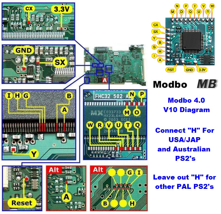
V10 Modbo modchip installation diagram
One of the last revisions of the fat PlayStation 2 was the V10. They were found in many of the SCPH-5000x models. They feature a quieter fan when compared to earlier models, and require some form of a laser fix. Matching console model numbers and board numbers are listed below.
You can find the model number on the sticker on the bottom of the console, and the board number is printed on the PS2 main board if you take apart your console. Note that there can be multiple board numbers within a specific model number.
- NTSC-J (Japan):
- SCPH-50000 (GH-026)
- SCPH-50005 (GH-026)
- SCPH-50007 (GH-026)
- NTSC-U/C (USA)
- SCPH-50001 (GH-026)
- PAL
- SCPH-50002 (GH-026)
- SCPH-50003 (GH-026)
- SCPH-50004 (GH-026)
Note that there are multiple versions of the Modbo modchips available, but the installation diagrams are all the same. Some example versions are Modbo 3.0, Modbo 4.0, Modbo 5.0, and Modbo 750.
For more information about Modbo modchips click here, for more information about PS2 modchips in general click here.
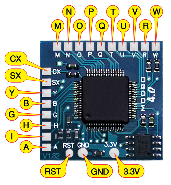
V10 Modbo installation diagram
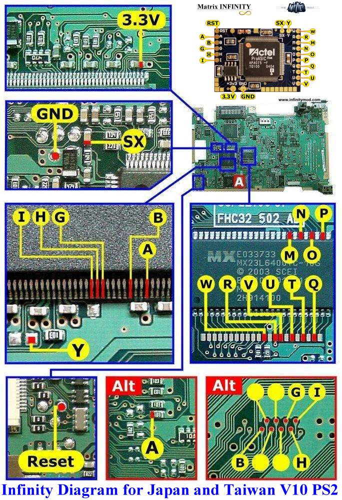
There is another V10 board layout (or maybe it’s a V11). Here is a diagram for that one:
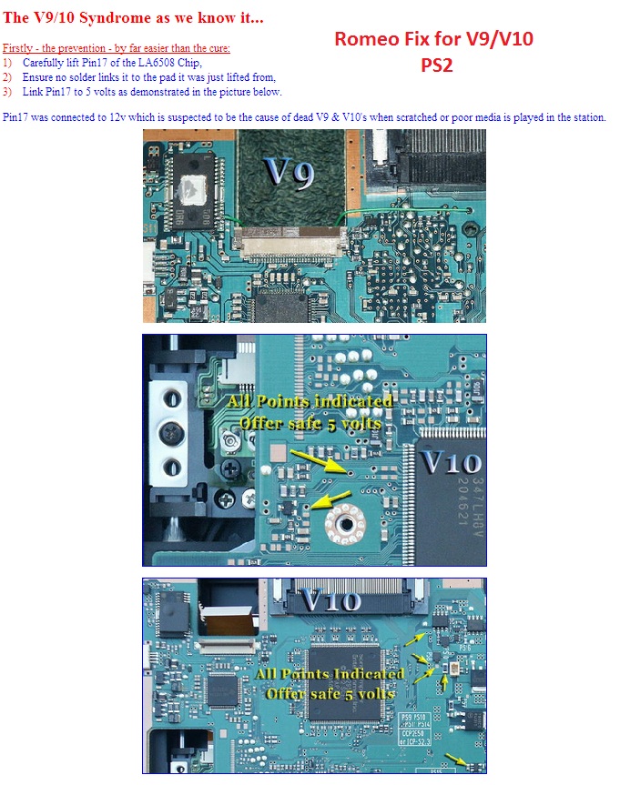
V10 laser fix diagram
There was a defect in the design of the V10 console that can cause the laser to burn out when playing back games once a modchip has been installed. There was a fix for this problem called the Romeo laser fix.
This fix involves lifting a pin on a chip, and then connecting that pin to a 5V point on the board.
Installation tips
Here are some tips I have for you when you are soldering your chip into a V10.
- Using 30 AWG solid core wire works well for most of the points.
- Use some thicker wire for the 5V and ground wires.
- Use even thinner wire for the I, H, G, A, and B points. 36 AWG enamel coated wire works well.
Example installations
This section has photos of some successful installations which you can use to get a better understanding of how everything is wired and positioned. Leave a comment and I’ll add your installation to the list
- William Quade (me)
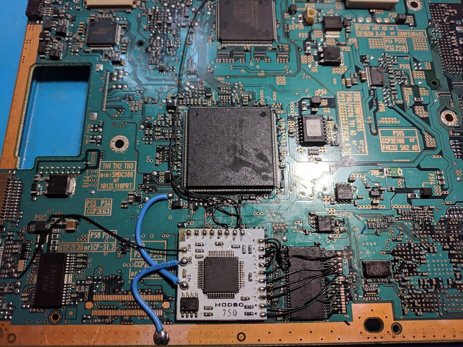
Done!
and the back side
OK, Heres my issue…. First, stats Modbo 5.0 V.9 pcb out of a 50001 Phat PS2 Everthing in, soldered up tight and tidy (or so the wires tell me) hooked up to test,…. 1). Unit starts to PS2 home screen, and controls function properly to navigate PS2 menus 2). Disc drive does not spin up, but the laser fires up moves to the spindle and shuts down 3). Cannot access the Modbo 5.0 config menu via circle and triangle. Anyone Have this issue? could this be something crossed up? Look harder for a bridge somewhere? thought I went through it… Read more »
If you aren’t able to get to the Matrix boot menu then at a minimum one or more of these wires isn’t right: M, N, O, P, Q, T, U, V, R, W
Those wires do the BIOS patching.
Same issue here i also soldered it secure and i use lot of flux to maintain good solder but the 4.0 and 5.0 modbo i mean the matrix logo not appear in screen
I’ve been going crazy trying to get it to work on my european PAL V10 and the Matrix splashscreen at the beginning would come up, and so did the modbo menu, but anything that wasn’t an original european PAL game would come up with red “insert PS2 disc” screen. I tried connecting “H” on the motherboard after a lot of other troubleshooting, eventhough it’s a european PAL, and it loads everything I put into it now!! Just need a new lens now…
After messing around checking my work over and over , i found this page and your comment , may pal v10 machine also wouldnt boot anything untill i connect the H point !!.
cheers 🙂
I’ll be Moding mine soon! I’ll let you know if it works for me or not.
Thanks William, just finished moding for the first time, it wouldn’t play Burnt games after the first attempt but when I opened it back up to see what I had done wrong and it was obvious. I had the board upside down in relation to your picture for the Alt B,G,H AND I connections, put them in the correct spot and all is good.
Thanks heaps buddy.
hey will, i notice that your example pic is a v9 but this page is for v10. have a look at the v10 install that i did today! – could you link this picture on this page?
EDIT: I used the same points as in your guide, except that I used alt points for power and ground
Hi, GH-026 successfully modded on 11/7/20.
bricked my 1st go at this on a ps2 slim so got a ps2 phat got most soldered to mobo but having trouble attaching the wire to the M point on the modbo 5 diagram, the little bugger will not attach
Flux helps if you aren’t already using it.
Yeah have been using it, turns out my soldering iron wasnt heating the tip up properly so gotta get a new 1