V1 Modbo modchip installation diagram
The earliest PlayStation 2 model that supports Modbo modchips is the V1 board revision. These also happen to be the very first revision sold in the United States. Matching console model number and board numbers are listed below.
You can find the model number on the sticker on the back of your console, and the board number is printed on the PS2 main board if you take apart your console. Note that there can be multiple board numbers within a specific model number.
- NTSC-U/C (USA):
- SCPH-30001 (GH-004)
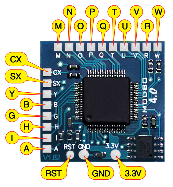
Note that there are multiple versions of the Modbo modchips available, but the installation diagrams are all the same. Some example versions are Modbo 3.0, Modbo 4.0, Modbo 5.0, and Modbo 750.
The V1 board revision may not be compatible with the newer Modbo 4.0/5.0/750 chips being sold today.
For more information about Modbo modchips click here, for more information about PS2 modchips in general click here.
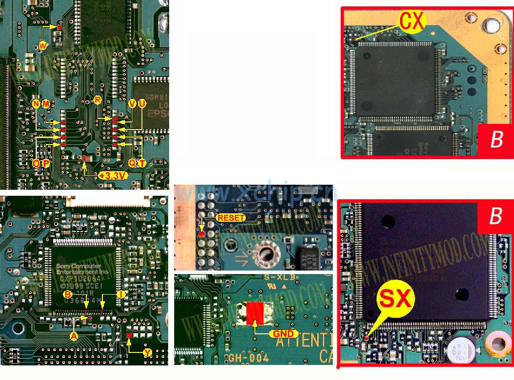
V1 Modbo installation diagram
Installation tips
Here are some tips I have for you when you are soldering your chip into a V1.
- Using 30 AWG solid core wire works well for most of the points.
- Use some thicker wire for the 5V and ground wires.
Example installations
This section has photos of some successful installations which you can use to get a better understanding of how everything is wired and positioned. Leave a comment and I’ll add your installation to the list
- Nobody yet.
Thought I’d add my v1 Modbo 5.0 install here. Not the cleanest but might help some of you trying to do the same. https://drive.google.com/drive/folders/1UXhJ-IDDr8sMyRYIpNENu6pw5GX1WFpl
Not the cleanest? Looks great manP
This diagram is missing the H and G locations. They are identical to the V2 variant.
Thanks, i spend a whole day rechecking my work cause it I was missing the H and G points. Once i added the those points, it works with no issue. Please update the diagram to reflect point H and G
Glad to hear it – I’m not sure if the admin is updating this anymore, might just be dead.
I have the V1 or V2 (not sure which, it’s not apart yet).
So your modbo works correctly? Which version of the modbo did you use with your V1?
The admin says Modbo may not work with anything before V5.
I have personally installed a Modbo 4.0 chip into a V1 without issues. The original people who sold the Modbo chips only really advertised that they’d work with newer models, from my experience they do work, but there just isn’t a whole lot of documentation or good diagrams at this point.
I have ordered a v4.0 modbo chip to install into my V1 system and will try and use this diagram to install. I have one question when disassembling the system I noticed the power pins are soldered together on the motherboard was this common on these model of systems. I have only ever modded Slim models this will be my first fat model system.
Yeah, that’s normal for this model (not a thing on the newer fat models though).
Cool just wanted to confirm
Is there an alternative point for I and B because I am trying to n install this amd thes point just hove other board peices to close to the to attempt to solder and not bridge anything. Thank you
There might be, probe around the board with a multimeter.
Will do i finally got it to go to the tiny pin