PU-8 PsNee modchip installation diagram
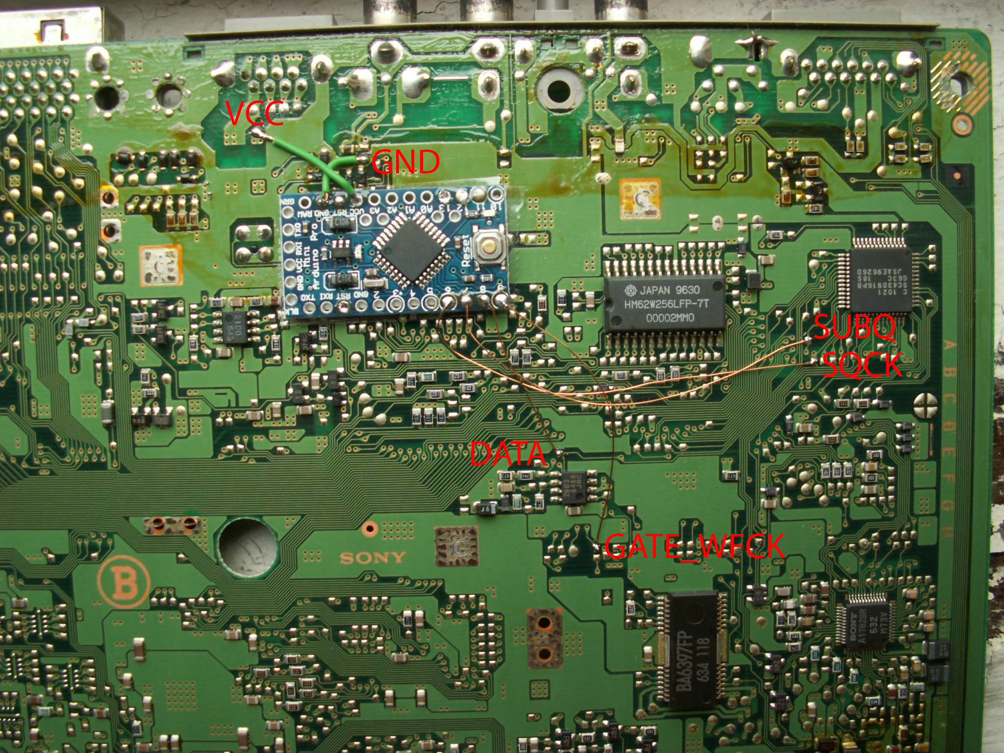
This was one of the earlier PlayStation 1 board designs that included RCA composite video output ports on the back. Most SCPH-1001’s here in the United States had this board inside.
Additionally many Japanese systems had this board including many SCPH-3000, SCPH-3500, and SCPH-5000’s.
For more information about PsNee chips click here, for more information about PS1 modchips click here.
PU-8 PsNee modchip installation diagram
Arduino pinout:
- Pin VCC – VCC
- Pin GND – GND
- Pin 3 – Debug TX
- Pin 4 – BIOS A18
- Pin 5 – BIOS D2
- Pin 6 – SQCK
- Pin 7 – SUBQ
- Pin 8 – DATA
- Pin 9 – GATE_WFCK
Above are two installation diagrams for two different versions of the PU-8. The easiest way to know which you have is to look at the size of the Mechacon controller chip (next to SUBQ and SCLK/SQCK). If it’s large, use the bottom diagram, if it’s small, use the top diagram.
Installation tips
Here are some tips I have for you when you are soldering your chip into the PU-8.
- Cut your wires to be as short and direct as possible.
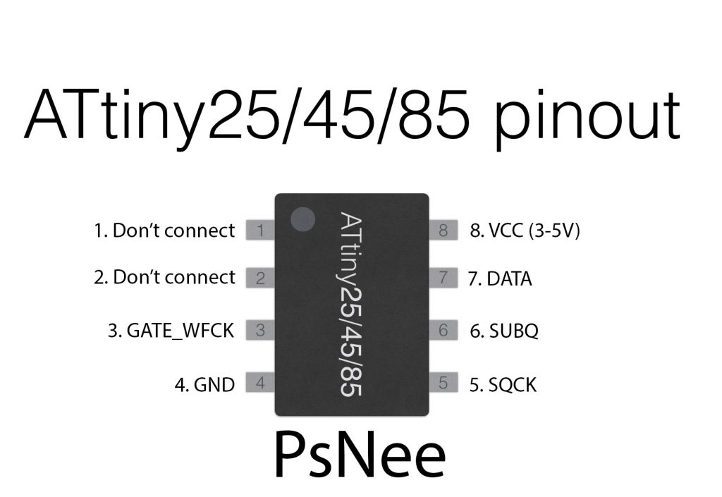
- You don’t need to connect pins one and two of the ATtinyX5 chip. Just desolder the wire.
- Use a multimeter to probe around for alternative VCC and GND points closer to where you position your chip for a cleaner installation.
- Try to position your chip towards the middle of where all the wires need to go, to minimize wire length.
Example installations
This section has photos of some successful installations which you can use to get a better understanding of how everything is wired and positioned.
- William Quade (me)
Ignore the larger board in the diagram, it’s a PSIO switchboard.
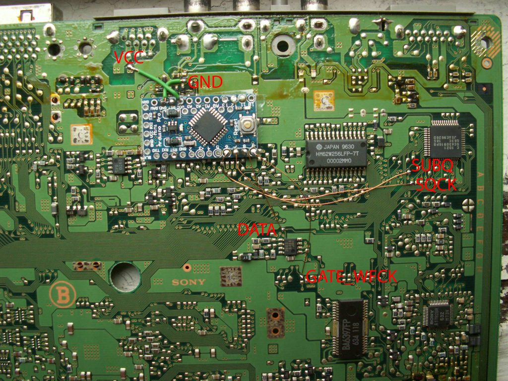
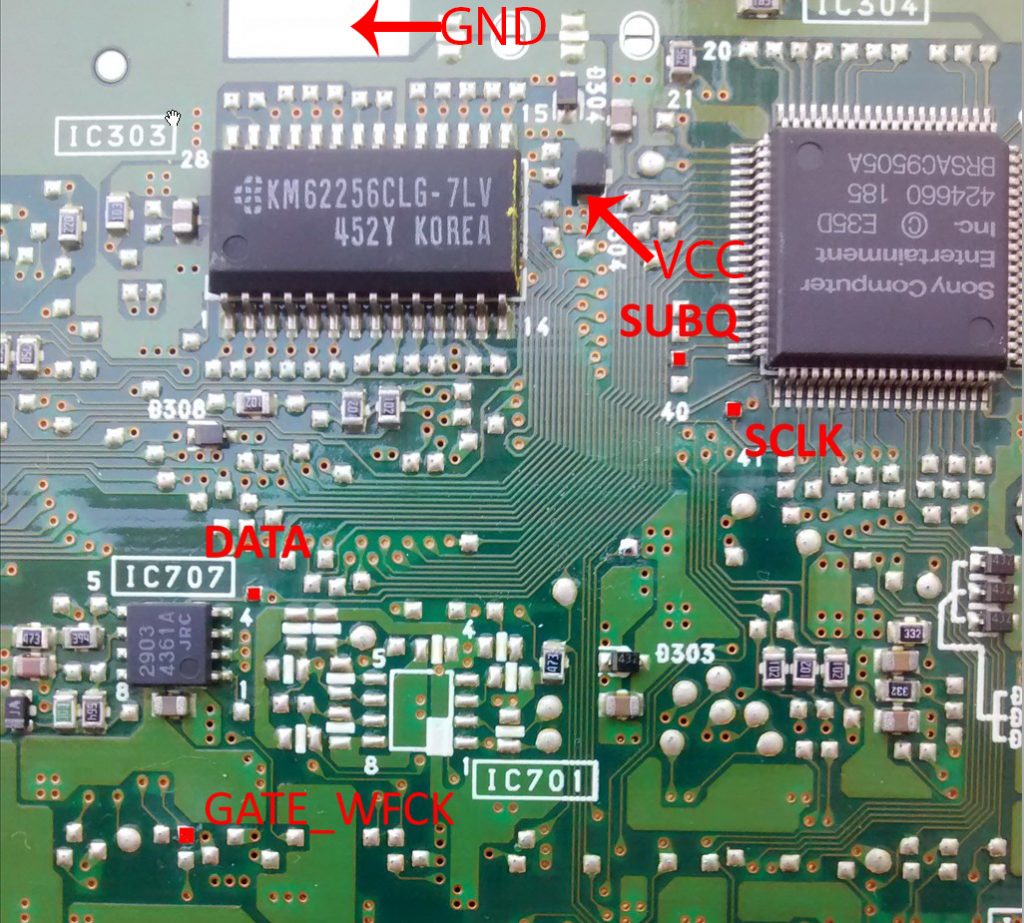
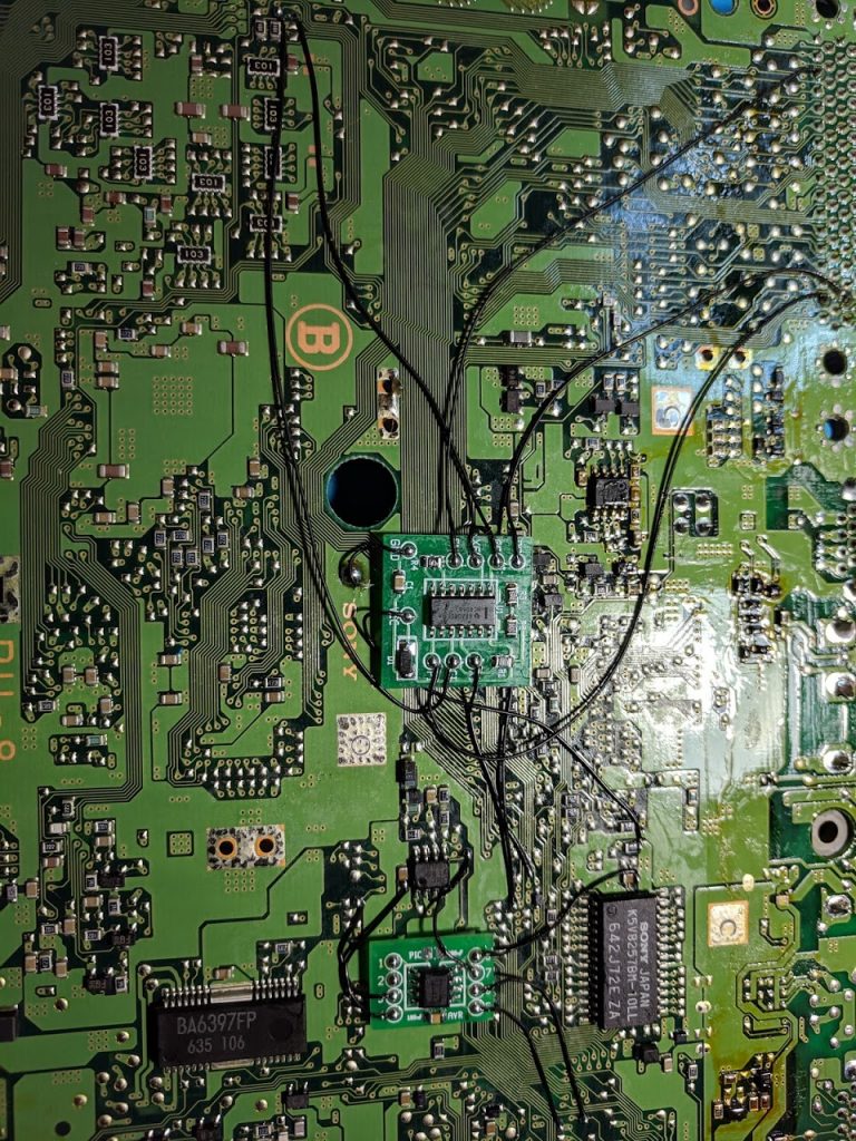
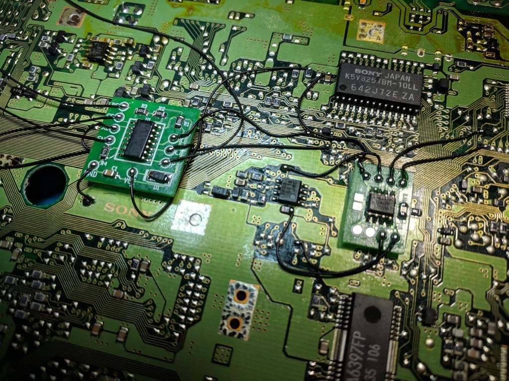
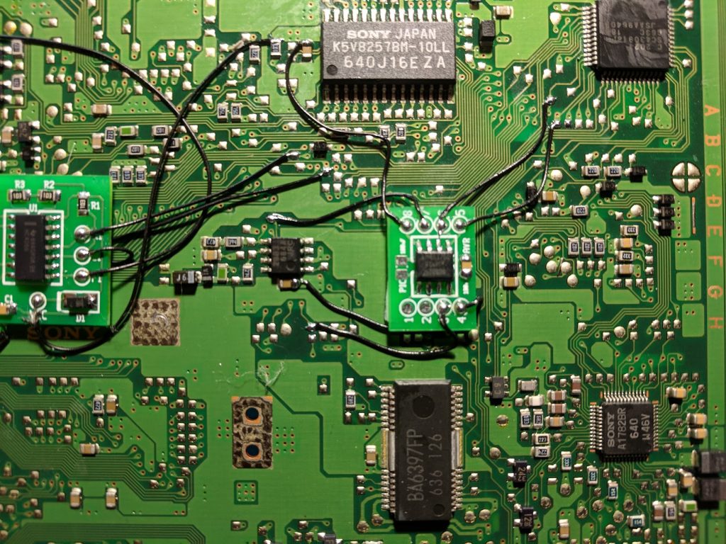
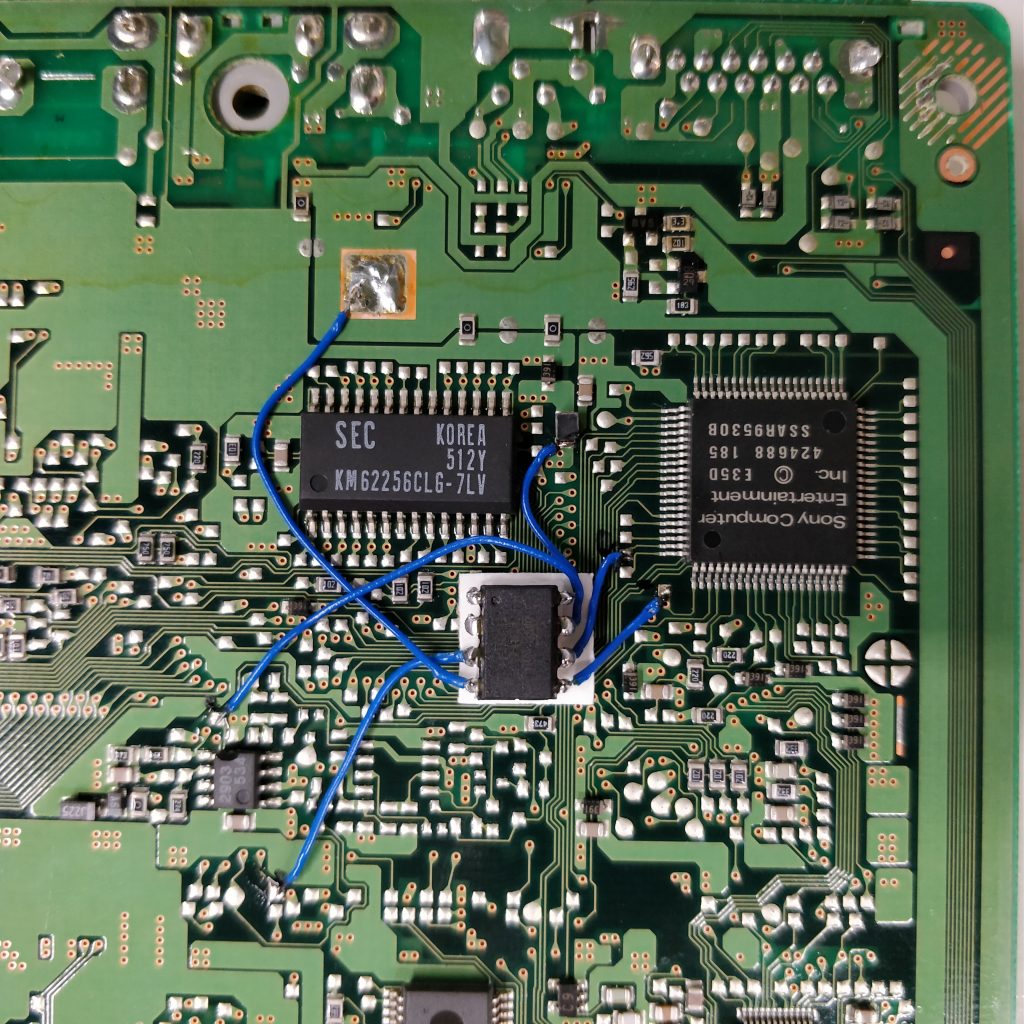
I’ve just successfully installed a PSNee in my SCPH-1001, but neither of the diagrams were correct for my PU-8 board. I ended up having to compare the two diagrams and make my best guess at where the points were, especially for DATA, GATE_WFCK, and SCLK. Here’s a pic of my finished install, hopefully it helps anyone else with this specific board: https://imgur.com/a/glRIOHV
You may edit and use this image as an example if you want.
Looks good, I put it in the list of example installations.
I have successfully installed the Arduino Pro Mini as well, as shown by Nall Wolf. PU-8 board. Initially, I made a mistake with the choice of the controller version and specified 16 MHz instead of 8 MHz in the Arduino IDE settings. As a result, even the original disks were not loading.
https://yadi.sk/i/yDtnGB98M35h5Q
Successfully chipped my SCPH-1001. Kind of used both images to do it and ended up taking ground off of the pin on the end of that RAM (I think) chip because it’s pretty close to where I put the PSNee and I think it looks pretty clean. Here’s the finished product and my own guide I made: https://imgur.com/a/HP45Mfw. Feel free to post them here so others can see.
Hey William, thanks for the PSNee modchip. I successfully installed mine using the same wiring configuration as Nall Wolf’s.
Thanks for the chip! I had the same variant board with the small controller.
https://imgur.com/a/cljQB93
Just got my PSNee i ordered in the mail today, and followed your install diagram in the first pic, as the motherboard matched mine… well it seems my system is dead now… Would like to know how it went wrong as I had an mm3 in there previously which went fine. the disc wouldn’t spin, then the video cut out and i get nothing. the system does power on though. so I don’t think its the fuse. after removing the chip i have the same result now. Any idea what went on the ps1 motherboard? the system is essentially dead.
There are many fuses on the board that can blow and cause certain things to stop working, not just the large main power input fuse. You probably should test the onboard fuses as well as look around the board for any accidental shorting from solder.
Thanks for the quick reply, I’ll see if anything looks off. I think what might have happened was I wrapped the chip in tape and a couple of legs poked through and might have shorted something. I’m using some heat shrink instead now to hopefully avoid another issue.
Hi William, thank you for this amazing guide to ps1 modchips. I just finished install my first modchip, this psnee. I replicate all your wiring but it is not working. Instead of reading burned discs or imports, it doesnt want to read anything at all! When I place a cd it will start spin it and then recognize it as music cd, or dont read it at all. Do you have a clue what the problem is? Maybe I did bad soldering? I adjunct a picture of the work I did, I hope you can see something I don’t and… Read more »
It’s not a good idea to have that much insulation stripped off the wires. It also looks like some of the solder connections may be cold solder connections that aren’t making a good reliable connection.
Hey there. I installed a PSNee on another SCPH-1001 and it works great! However, I’m having trouble on the 2nd one and can’t seem to shake it. Everything plays correctly but the sound has an ever present crackle (mostly on the FMV clips) I have gone through all my connections and replaced the laser assembly twice as well as tried it on other SCPH-1001’s. They work on those. Is this a possible cap replacement needed? Or, some type of interferance? the crackle is the same on the RCA ports as well. I’m super stumped
Yeah, that sort of sounds like a hardware issue like bad caps.
That’s kinda what I thought also. I guess I’ll just recap if. Thanks!
My PU-8 board is also as shown by Nall Wolf. Thank you both for the inspiration and hand holding. I’m now enjoying the Japanese classic ‘densha de go’ on my PAL playstation.
Mine was successful, although I’m having a strange issue playing PAL games. As soon as Licensed by Sony screen goes away, the image just goes pitch black and I get no audio or anything. My other later model PS1s work fine with PAL games, but not this one. Is this just a hardware issue with these models?
Are you using composite video for both systems? Composite video will be black and white for PAL games on an NTSC system.