PU-7 PsNee modchip installation diagram
The PU-7 was the very first PlayStation 1 board that was released. It is found on all Japanese SCPH-1000’s, along with some SCPH-1001’s, SCPH-1002’s, SCPH-3000’s, and SCPH-3500’s.
This board is unique because it has the pins for S-Video video output along with the RCA video output ports. The S-Video port was only available on the Japanese SCPH-1000, but the pins are still on other systems with the PU-7 board.
For more information about PsNee chips click here, for more information about PS1 modchips click here.
PU-7 PsNee modchip installation diagram
Arduino pinout:
- Pin VCC – VCC
- Pin GND – GND
- Pin 3 – Debug TX
- Pin 4 – BIOS A18
- Pin 5 – BIOS D2
- Pin 6 – SQCK
- Pin 7 – SUBQ
- Pin 8 – DATA
- Pin 9 – GATE_WFCK
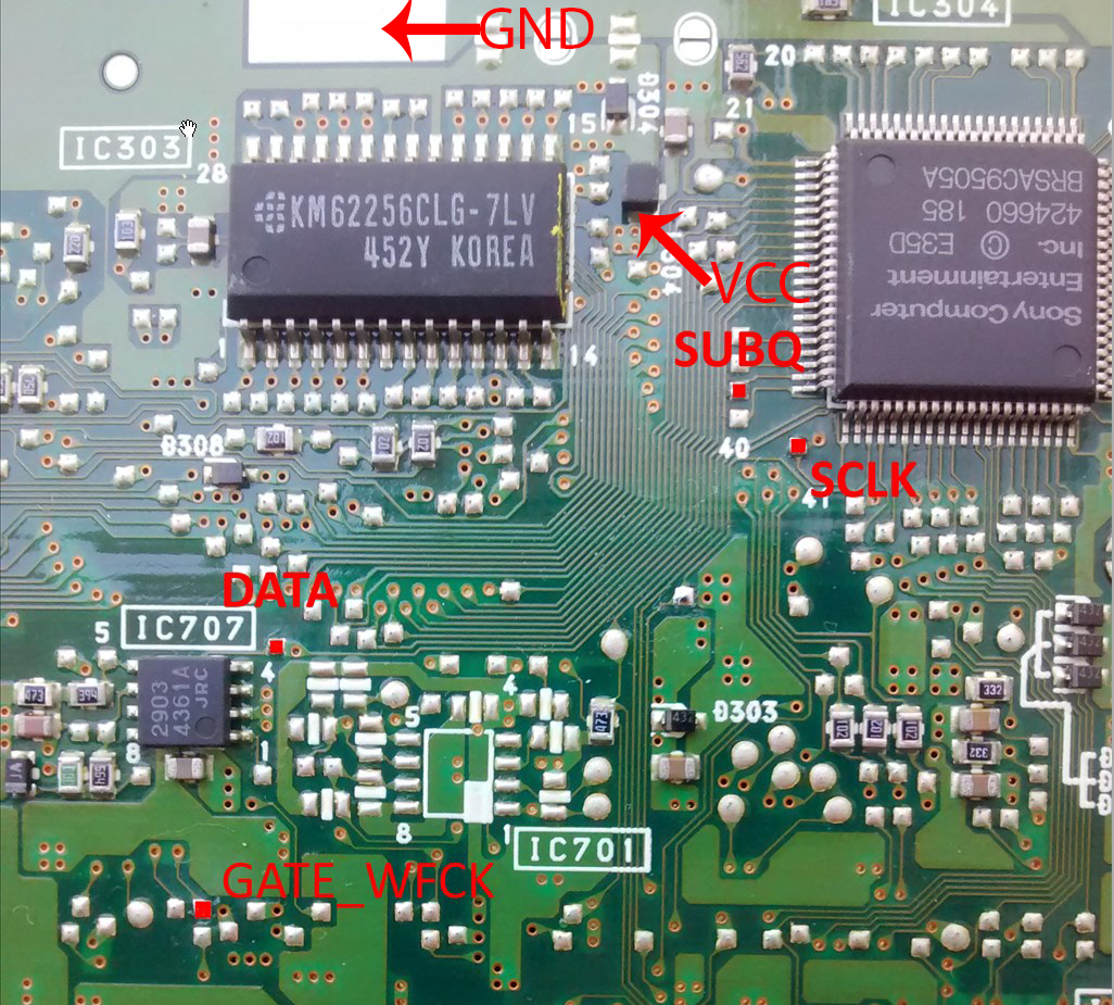
Above is the diagram for the PU-7.
All of the points being soldered to are pretty straightforward pads. They are all located on the bottom side of the board. The PsNee is a great chip for the PU-7 because it supports anti-modchip games. The Mayumi V4 isn’t compatible with the PU-7 at all, and the MM3 doesn’t support stealth mode with the PU-7.
Installation tips
Here are some tips I have for you when you are soldering your chip into the PU-7.
- Cut your wires to be as short and direct as possible.
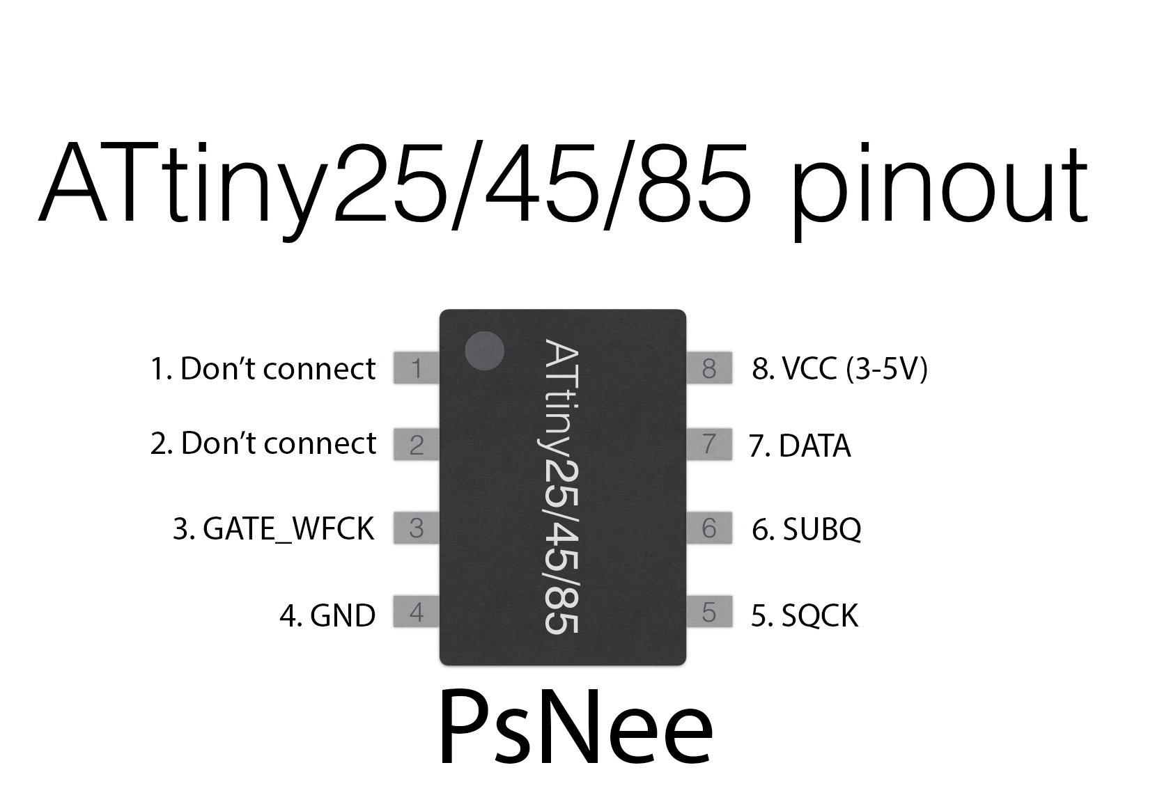
- You don’t need to connect pins one and two of the ATtinyX5 chip. Just desolder the wire.
- Use a multimeter to probe around for alternative VCC and GND points closer to where you position your chip for a cleaner installation.
- Try to position your chip towards the middle of where all the wires need to go, to minimize wire length.
Example installations
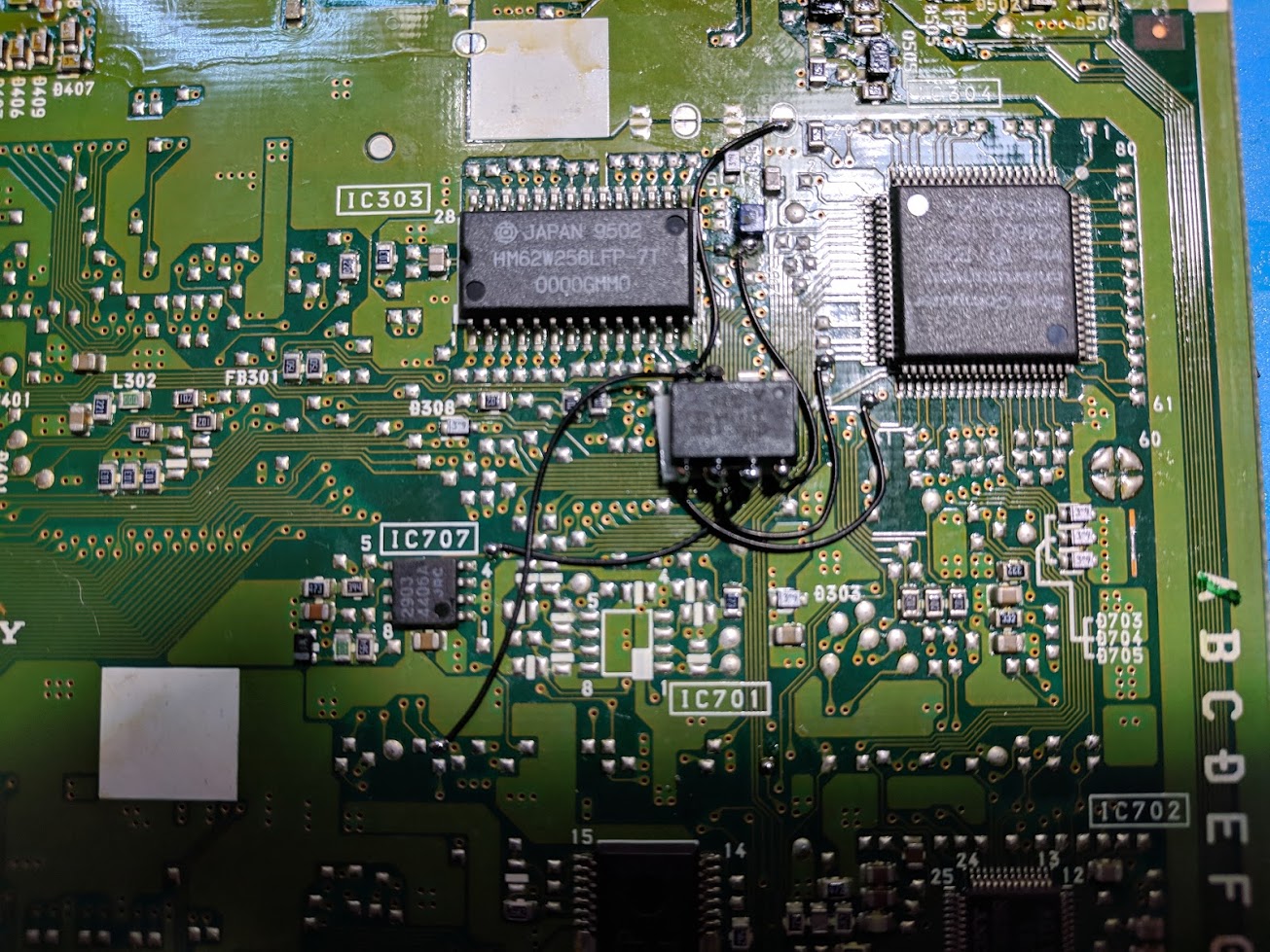
This section has photos of some successful installations which you can use to get a better understanding of how everything is wired and positioned.
This is an installation I did on an SCPH-1000:
can this play pal games with the 1 or the other crystal?