PU-23 PsNee modchip installation diagram
The last version of the original PlayStation 1 design was the SCPH-900x. Most of these consoles have PU-23 boards inside. The most notable difference between the 9000 series and earlier consoles is that Sony removed the parallel IO port on the back. They also shrunk down the size of the board significantly.
For more information about PsNee chips click here, for more information about PS1 modchips click here.
PU-23 PsNee modchip installation diagram
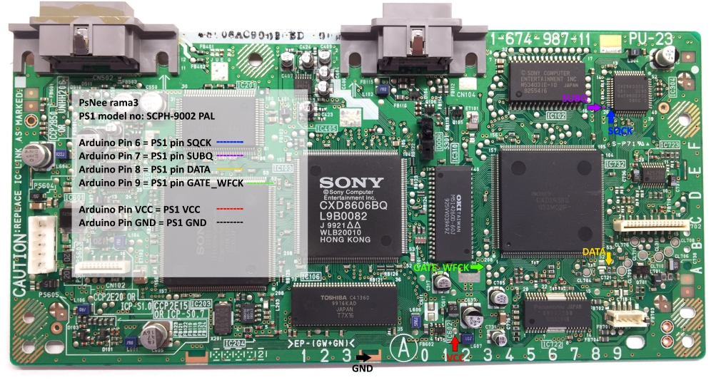
Arduino pinout:
- Pin VCC – VCC
- Pin GND – GND
- Pin 3 – Debug TX
- Pin 4 – BIOS A18
- Pin 5 – BIOS D2
- Pin 6 – SQCK
- Pin 7 – SUBQ
- Pin 8 – DATA
- Pin 9 – GATE_WFCK
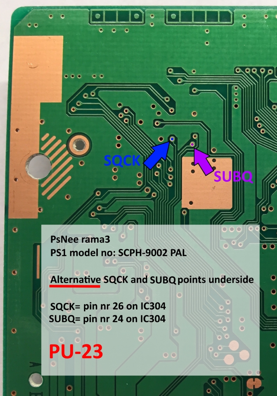
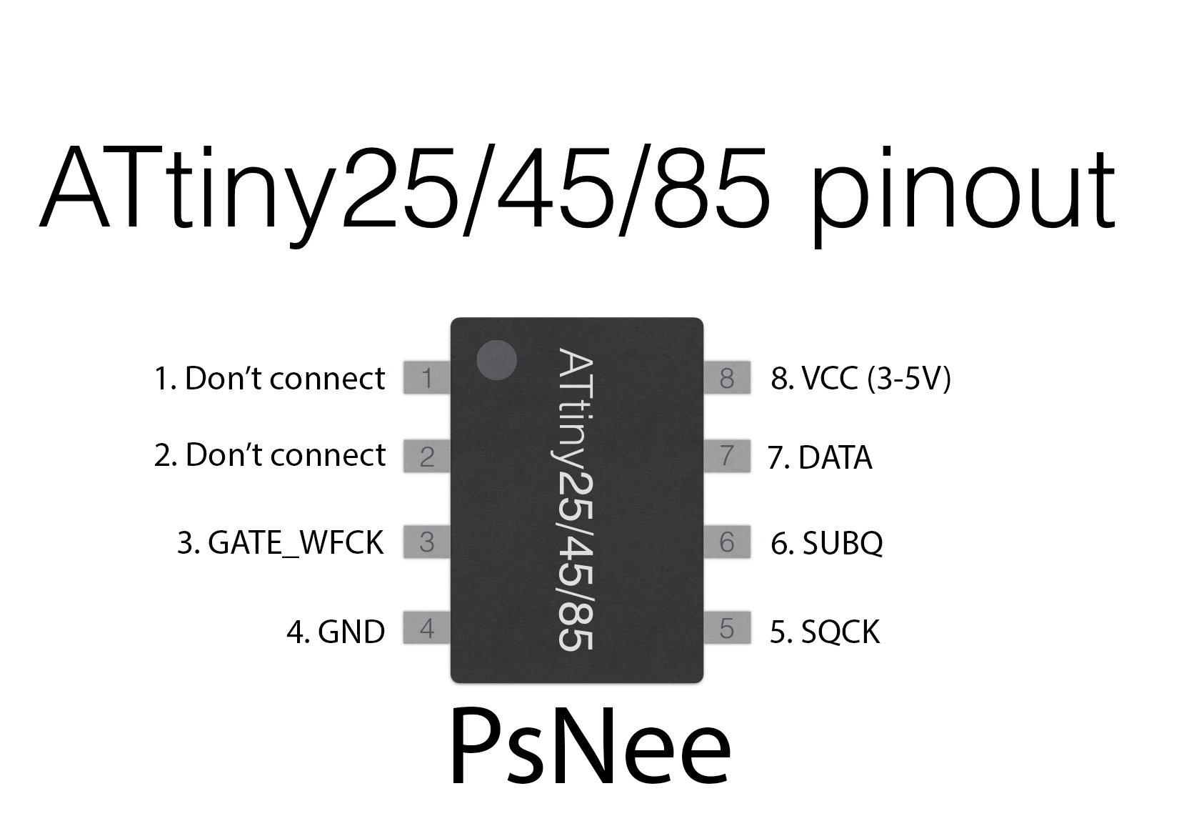
Above are some diagrams for installing the PsNee into a PU-23. The first diagram shows the pinout of the ATtiny45, the second shows the installation diagram (including pin numbers for Arduino users), and the third shows some alternative points. Click on an image to open it in a new tab where you can zoom in to get more detail.
Let me know if any of the points aren’t clear, I can clarify them for you.
Installation tips
Here are some tips I have for you when you are soldering your chip into the PU-23.
- Cut your wires to be as short and direct as possible.
- You don’t need to connect pins one and two of the ATtinyX5 chip. Just desolder the wire.
- Use a multimeter to probe around for alternative VCC and GND points closer to where you position your chip for a cleaner installation.
- For DATA, be careful not to bridge the connection to the other resistor next to the one you are soldering to.
- Don’t apply too much solder to SQCK, or you’ll bridge the pins on the chip.
- For the wires that go into the holes, or vias, of the board: it’s easiest to stick a small 30 AWG wire through the hole, then heat the wire and hole while adding solder.
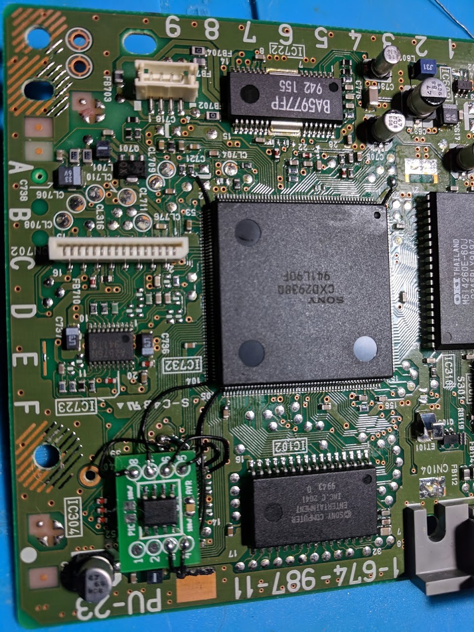
- Placing the chip on top of the chip above SUBQ and SQCK is a good spot.
Example installations
This section has photos of some successful installations which you can use to get a better understanding of how everything is wired and positioned.
- William Quade (me)
I hope it helps someone:
If you want to use an arduino nano, you have to erase the bootloader. To erase the bootloader you have to write the code with an isp if not it is not going to work.
i’m leaving on this link some pics of te instalation i made
link: https://mega.nz/#F!DGIygCbD!hTUX5TXdciOeCU9eNkX5hw
Elsalas55 thank you!
I accidentaly remove the resistor on data connection… anybody knows the value for him?
It’s a 100k-ohm resistor.
Hello!
Do you have any idea why can’t read my scph-9002 any NTSC game? It just stuck on the second screen. My another scph-7502 with psnee plays any of these disks. And It can’t be nor laser or disk problem because it is reading easily crappy audio discs and I played some PAL games on it without any problem. I’ve used the same psnee code on both of them with an arduino mini.
Thank you for any advance!
I’m not sure, it shouldn’t have any issues playing NTSC games. You’ll want to make sure all of the pins are properly connected.
I’d done checking, and It didn’t change on anything, but at least I did an acceptable job first time. I think the problem is the laser. I don’t have oscilloscope to adjust the laser. I think it is also pointless because after 55xx series the laser can adjust it self if I’m not wrong. I could be wrong but I can’t explain why it can’t read some games from the same type of medium quality verbatim disc. It can’t read any low quality maxell only recognize it audio disc. Some game (RE I (original us version), Medievil I (us)) disc… Read more »
After the 55xx the laser can adjust itself more than before, but there is still a single adjustment point on the laser ribbon cable itself which you can adjust.
You could always try playing the cheapest NTSC import game you can find to see if it will work. Since it’s a genuine game it should work with worn lasers.
Heres a pic of my install
http://imgur.com/gallery/3Bh49OG
Hi,
Just wanted to say thanks for the excellent documentation. PsNee’d my own ATtiny85 and installed using this guide and magnet wire. Worked first attempt on PU-23 board.
Thanks!
Excellent work on the guide. I’ve got a PU-23 board which I’m trying to mod, but the GATE_WFCK pad is missing, are there any alternatives, apart from the leg of the IC?
I’m pretty sure the only other place is the leg of the IC.
I’m having some confusion about the images above. On the first image indicating solder points, VCC and GND are at the bottom of the board. On the subsequent image of the finished install, the VCC and GND appear to be soldered directly under the chip location. Please clarify.
You can use any VCC point as VCC and any GND point as GND. There are many spots on the board that connect to the same place for all of the pins.
For board 9001 is there a alternate data (yellow) solder point? I am traumatized with them small ass resistors. 😀
If you follow the trace up the board a bit you’ll see it connects to a capacitor (try zooming in on the example installs to see). It’s another small component though so you’ll need to be careful.
Hi, I’m using an Arduino uno and I beilive i”m doing everything correctly and cant get it to work, ive tried every version of psnee i could find and no dice. Any tips?
I’ve only used the ATtiny version so I don’t have much to say. You might have better luck asking on the PsNee github.
Thanks; worked fine for me. Photos of the installation here: http://thp.io/2020/psnee.html