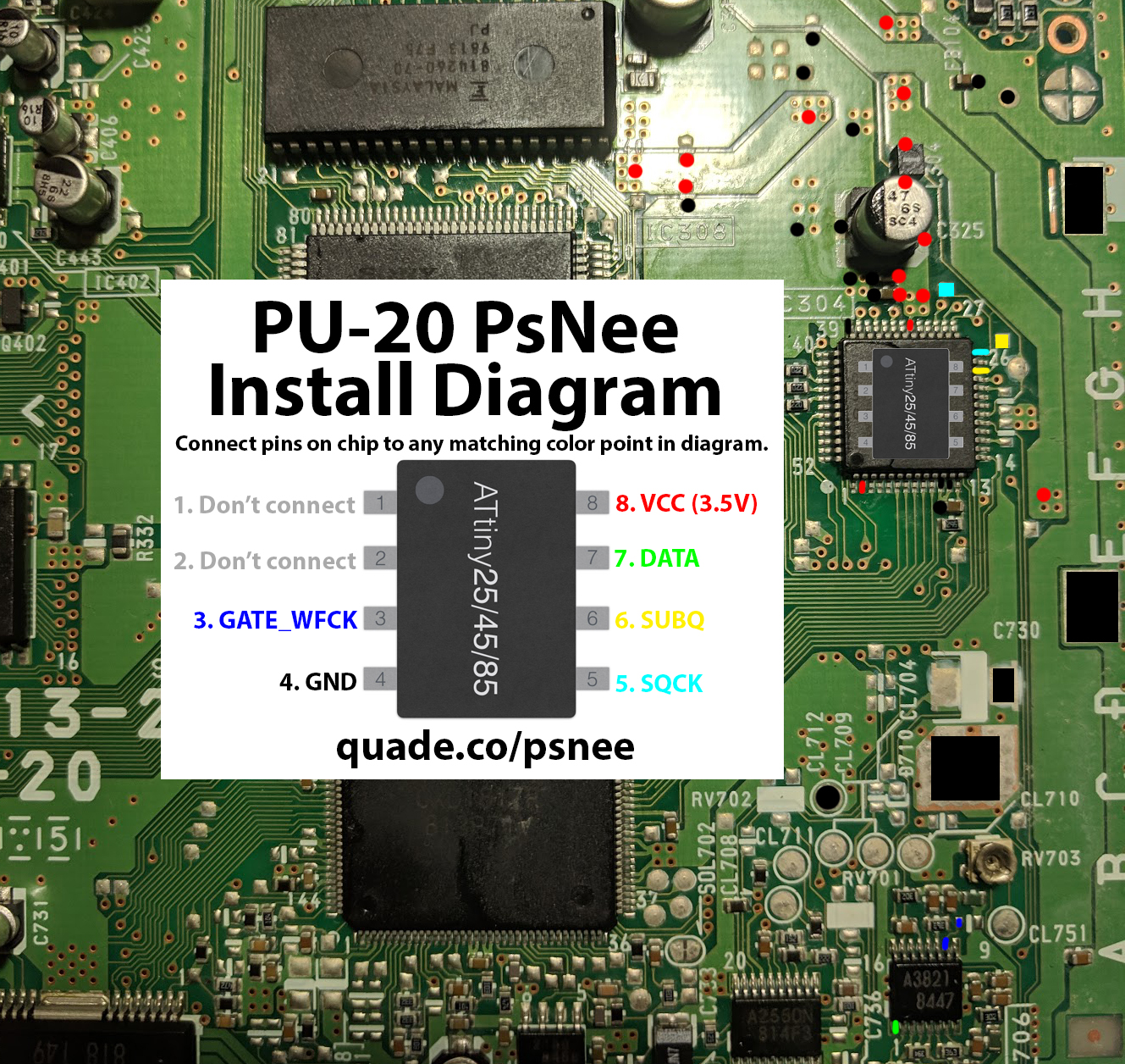
PU-20 PsNee modchip installation diagram
This board was used exclusively with the SCPH-7000 series of consoles.
For more information about PsNee chips click here, for more information about PS1 modchips click here.
PU-20 PsNee modchip installation diagram
Arduino pinout:
- Pin VCC – VCC
- Pin GND – GND
- Pin 3 – Debug TX
- Pin 4 – BIOS A18
- Pin 5 – BIOS D2
- Pin 6 – SQCK
- Pin 7 – SUBQ
- Pin 8 – DATA
- Pin 9 – GATE_WFCK
Above is the installation diagram for the PU-20. Just match each colored pin label in the diagram with any matching colored point on the board. There is a second image of the chip in the diagram showing a good place to position the chip.
Installation tips
Here are some tips I have for you when you are soldering your chip into the PU-20.
- Cut your wires to be as short and direct as possible.
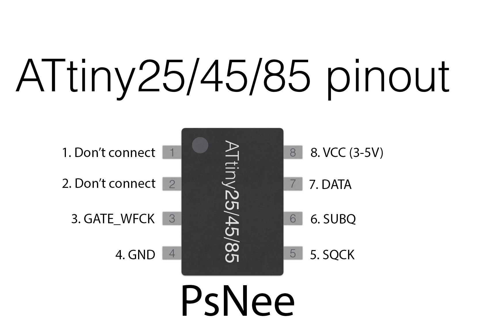
- You don’t need to connect pins one and two of the ATtinyX5 chip. Just desolder the wire.
- The DATA pin can be trickier to solder, make sure you don’t use too much solder or you risk bridging pins on the chip.
Example installations
This section has photos of some successful installations which you can use to get a better understanding of how everything is wired and positioned.
- William Quade (me)
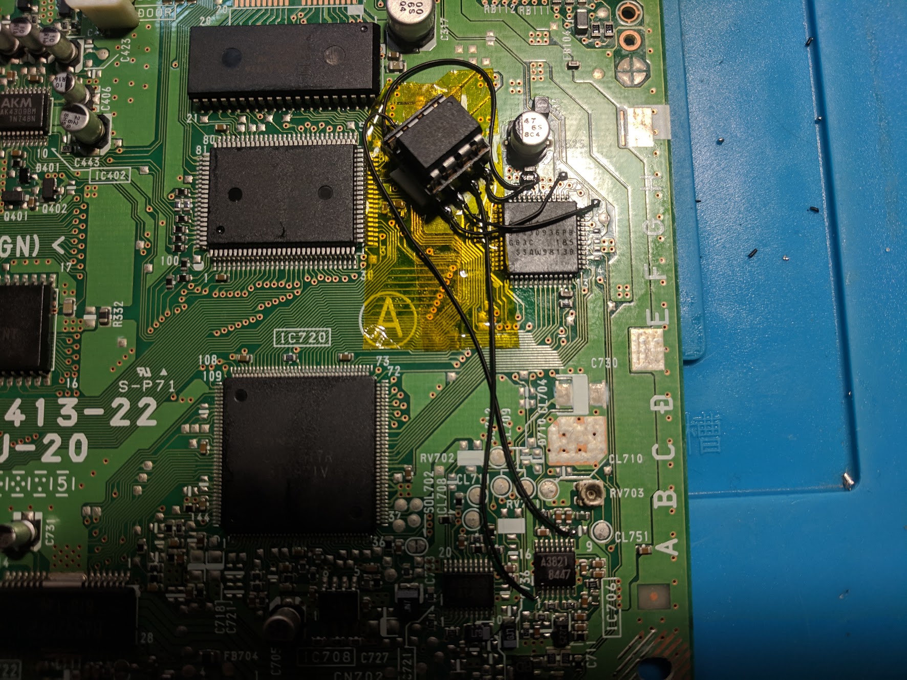
This is an example of an installation I did in a PU-20 using a socket. Using the socket allows me to test chips, and test new PsNee code. Note that the chip is a little too tall and prevents the top metal shield from going on all the way.
Hello,
Thanks so much for guide, it was very useful!
I did it successfully on my PS1 PU-20 😉
will it work with an Arduino nano
It should.
Another success with this guide. If you put the chip down near the cluster of testpoints like this, it fits through a convenient cutout in the shield even with a socket. Try not to mess with nearby RV703 though as it’s adjustable and will throw analog circuitry out of alignment if you turn it…