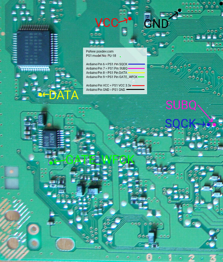
PU-18 PsNee modchip installation diagram
This board was used with a wide range of consoles from the SCPH-5000’s, and SCPH-5500’s, to even some SCPH-7000’s and SCPH-7500’s.
For more information about PsNee chips click here, for more information about PS1 modchips click here.
PU-18 PsNee modchip installation diagram
Arduino pinout:
- Pin VCC – VCC
- Pin GND – GND
- Pin 3 – Debug TX
- Pin 4 – BIOS A18
- Pin 5 – BIOS D2
- Pin 6 – SQCK
- Pin 7 – SUBQ
- Pin 8 – DATA
- Pin 9 – GATE_WFCK
Above is the diagram for the PU-18.
All of the points are fairly easy to solder to.
Installation tips
Here are some tips I have for you when you are soldering your chip into the PU-18.
- Cut your wires to be as short and direct as possible.
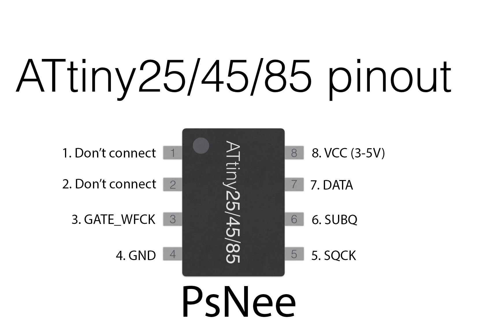
- You don’t need to connect pins one and two of the ATtinyX5 chip. Just desolder the wire.
- A good place to put the chip is underneath where the legend is, towards the middle of everything.
- Use a multimeter to probe around for alternative VCC and GND points closer to where you position your chip for a cleaner installation.
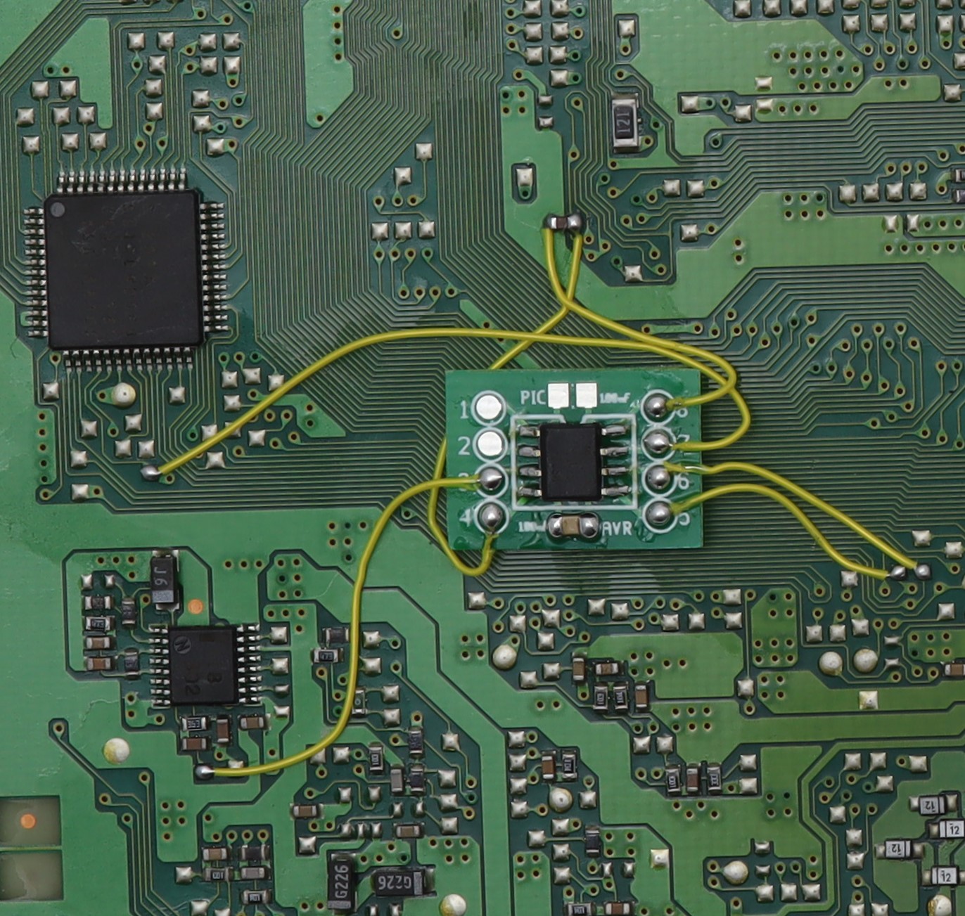
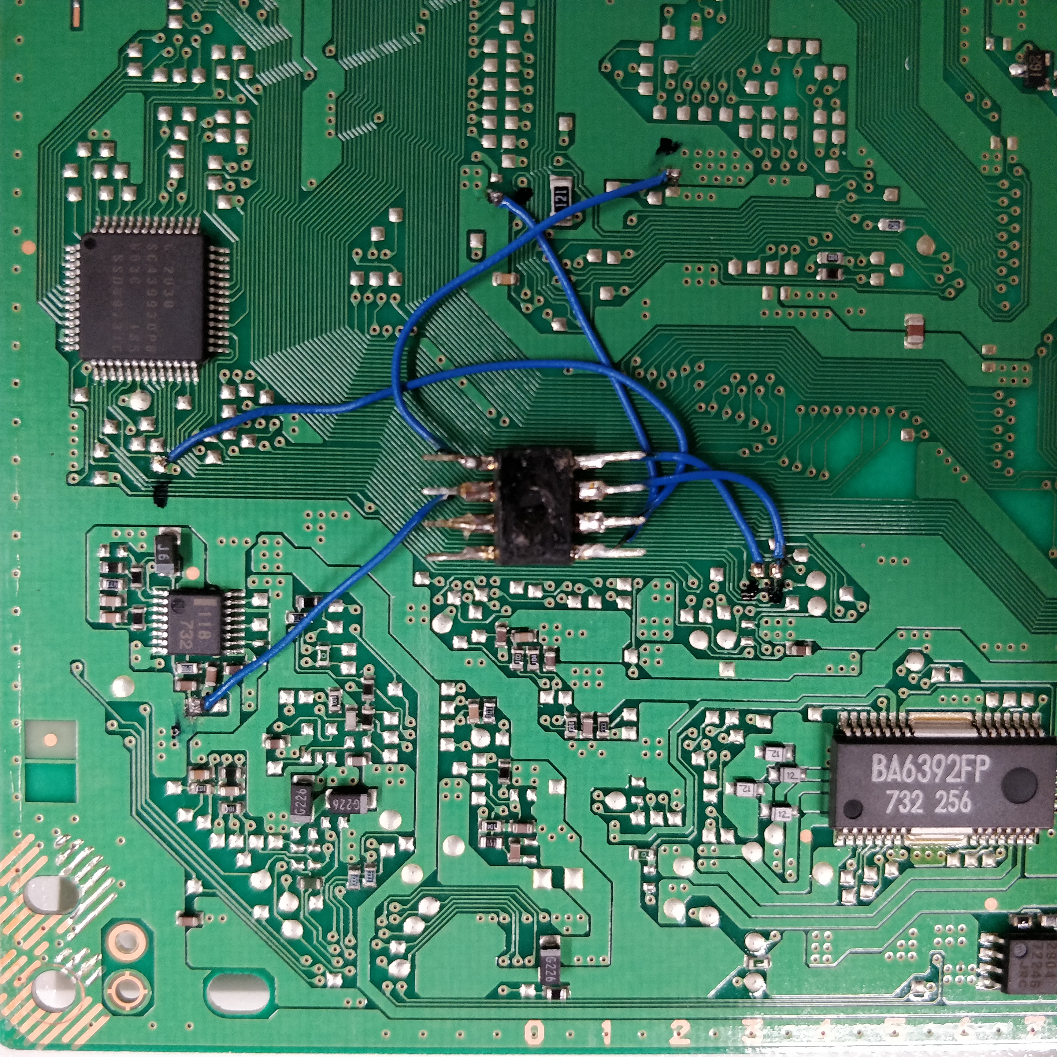
Example installations
This section displays example installations to help you get a better understanding what a successful installation looks like.
- William Quade (me)
- Nall Wolf
Alright, so this tutorial is great, i finally got it working with an Arduino Nano. I’m going to leave this information here if anyone rips up the pad for DATA and SUBQ. Both of these lead to the CD-ROM SUB CPU BIOS (The chip is above the DATA connection). For DATA, wire one end to the 4th pin from the left (Bottom side of CD-ROM SUB CPU BIOS) and the other to hole right of the pad. Or you can wire the other end to the 1st pin on the left side of the (4 CHL ANLG DEV) – (The… Read more »
Found your site quote helpful while researching PS1 modchips so I thought I’d give back and share my Arduino install, used a pro mini clone for mine. My wire routing isn’t the best but I stand by ‘fugly but functional’, and it works fine. I’d tried the pic mod chips previous but I think I have a bad programmer as they never worked.
https://postimg.cc/r0S71tK8
This diagram worked perfectly. Only took about a half hour maybe 45 minutes and I was playing some Pepsi Man and all my 100% legal backups. Thank you.
Yet another successfull install thanks to your guide ! Attiny45 on a 5502, install pic here : http://fichiers.arthus.net/psxdev/modchips/psnee/pu-18-psnee-attiny-mod.jpg
Cheers !
Ps1 will no longer read discs after install, tested with 2 known working cd drives and a few games and cd’s. No shorts to adjacent pads and chip is properly oriented. Did I get a chip with no firmware? Psnee https://imgur.com/a/4vjTeCP
Does it work if you remove the modchip?
Used the guide to install a PsNee in my 5501, works great (as long as you don’t accidentally swap VCC and GND the first time… Oops!). Here’s a pic of my finished, working install. Don’t mind the grossness on the chip, that’s melted Scotch tape residue caused by my mistake I mentioned earlier.
https://imgur.com/a/78khP1v
Looks good. I added the installation to the list of examples.
Worked for me!
Hello I have issue getting my PsNee Arduino working. I installed it booted a back up no problem the first time. Swapped the game out for another back up and it wont read any back ups or the first that read as a game. I have adjusted laser. It will go to cd menu and play the disc as audio but not boot into game. Any help would be great. My PS1 is 5501 PU18
Sounds sort of like a worn out laser.
Diagram is good. Hardest part for me was my insufficient solder/bad iron IDK wth it is. But finally got it after switching to another solder. Used loctite mounting putty to stick down and keep wires in place on PCB.
Hi unfortunately i need some
Help looping for another point on the bd to solder WFCK?
Thx
Found my way with mm3 diagrams point 5 for gate WFCK
Here my bd with the psnee, works fine!
Here the picture!
Hi, i already follow any instruction. Iak using attiny 45 with 8mhz internal.
But my ps1 still not working with copy disk. Btw my ps1 is scph 5500 japan.
Japanese systems have additional region locking in the BIOS. So only Japanese region games will work even with a modchip. So make sure you are using Japanese region backups.
Happened to rip off the pad for SQCK. Think I need some smaller wire and a bit smaller tip for my soldering iron too, haha. Are there any good alternative pads for SQCK? It’s a bit tricky to probe afterwards since the pad indeed is gone… Do I need to run a wire all the way from the other side of the board somewhere?
If you look at the example installations you can see that there is a small via hole that the pad connects to through a small trace.
Thanks for the quick reply! Yeah, I gave that one a go but decided it’s better that I get that smaller soldering iron tip first. Since it doesn’t have any solder on it from the factory it might be beyond my current equipment. So I think I’ll just try to patiently wait until I get a better tip for the job.
Well, patience isn’t one of my strengths so I just went up and used the soldering iron tip I have. I got a backup cd to load up and seems like everything is working the way it should. However I hardly get further from the region check. Load times are extremely long but it’s more likely related to the 20 something year old laser. Just a thought however: is there any chance that the modchip could lower some of the voltages driving the optical drive? That, or I accidentally turned one of the trim pots while installing the mod. Maybe… Read more »
Really long wires and bad soldering can sometimes make the system have issues loading games, but (as you guessed) it’s also very common for the laser to be the issue. As soon as it gets past the white logo screen and moves onto the black logo screen it’s all up to the laser. Old lasers can have trouble reading backups in particular since they are harder to read than genuine discs.
Hello all) Could you give a hex file for attiny 45?
I don’t have anything for the ATtiny45. Just compile it yourself with the Arduino IDE. There are instructions in the .ino file on the PsNee Github: https://github.com/kalymos/PsNee