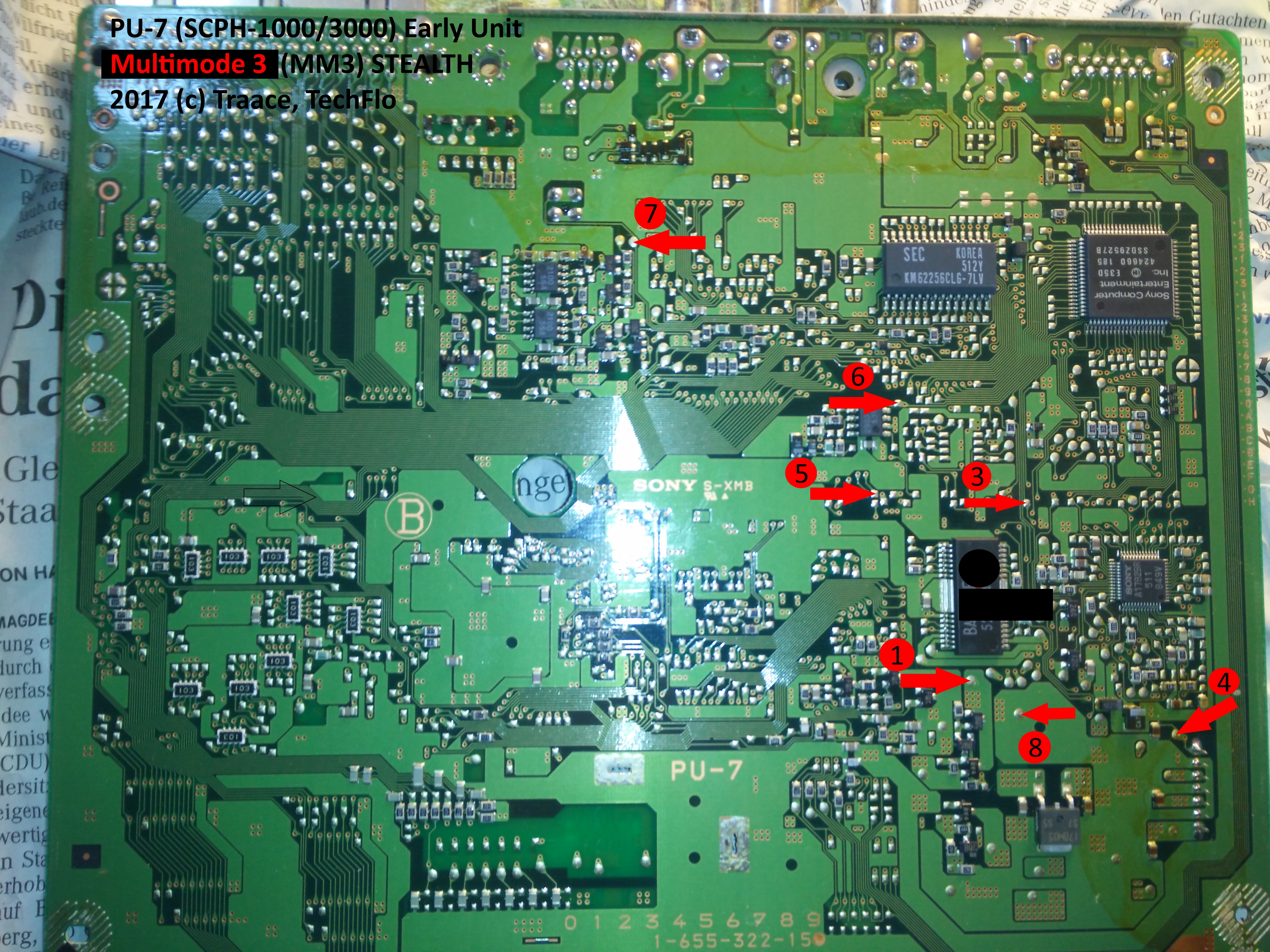
PU-7 MM3 modchip installation diagram
The PU-7 was the very first PlayStation 1 board that was released. It is found on all Japanese SCPH-1000’s, along with some SCPH-1001’s, SCPH-1002’s, SCPH-3000’s, and SCPH-3500’s.
This board is unique because it has the pins for S-Video video output along with the RCA video output ports. The S-Video port was only available on the Japanese SCPH-1000, but the pins are still on other systems with the PU-7 board.
For more information about MM3 chips click here, for more information about PS1 modchips click here.
PU-7 MM3 modchip installation diagram
Above is the diagram for the PU-7.
All of the points being soldered to are pretty straightforward pads. They are all located on the bottom side of the board.
I recently installed a chip in a slightly different PU-7 board and it functions (backups, and games from other regions boot), but the stealth functionality doesn’t seem to fully work (Spyro 3 displays the anti piracy message after it starts).
Installation tips
Here are some tips I have for you when you are soldering your chip into the PU-7.
- Cut your wires to be as short and direct as possible.
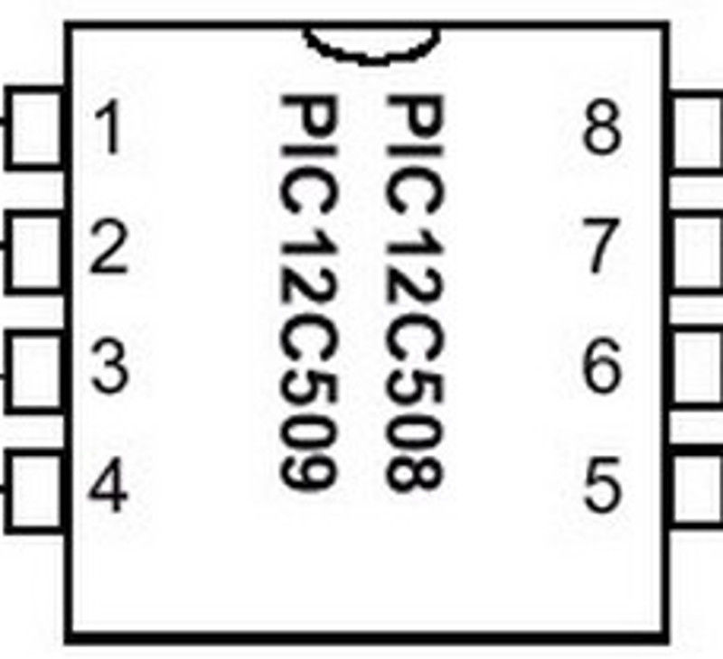
- Don’t connect pin two of the chip to anything.
- Pin 4 can either be connected to the pin 4 location in the diagram, or pulled high by connecting it to pin 1 on the chip.
- Placing the chip towards the middle of all of the pads you need to solder to is ideal. If you flatten the legs on the chip it will fit underneath the board without any modifications.
Example installations
This section has photos of some successful installations which you can use to get a better understanding of how everything is wired and positioned.
This is an installation I did on an SCPH-1000:
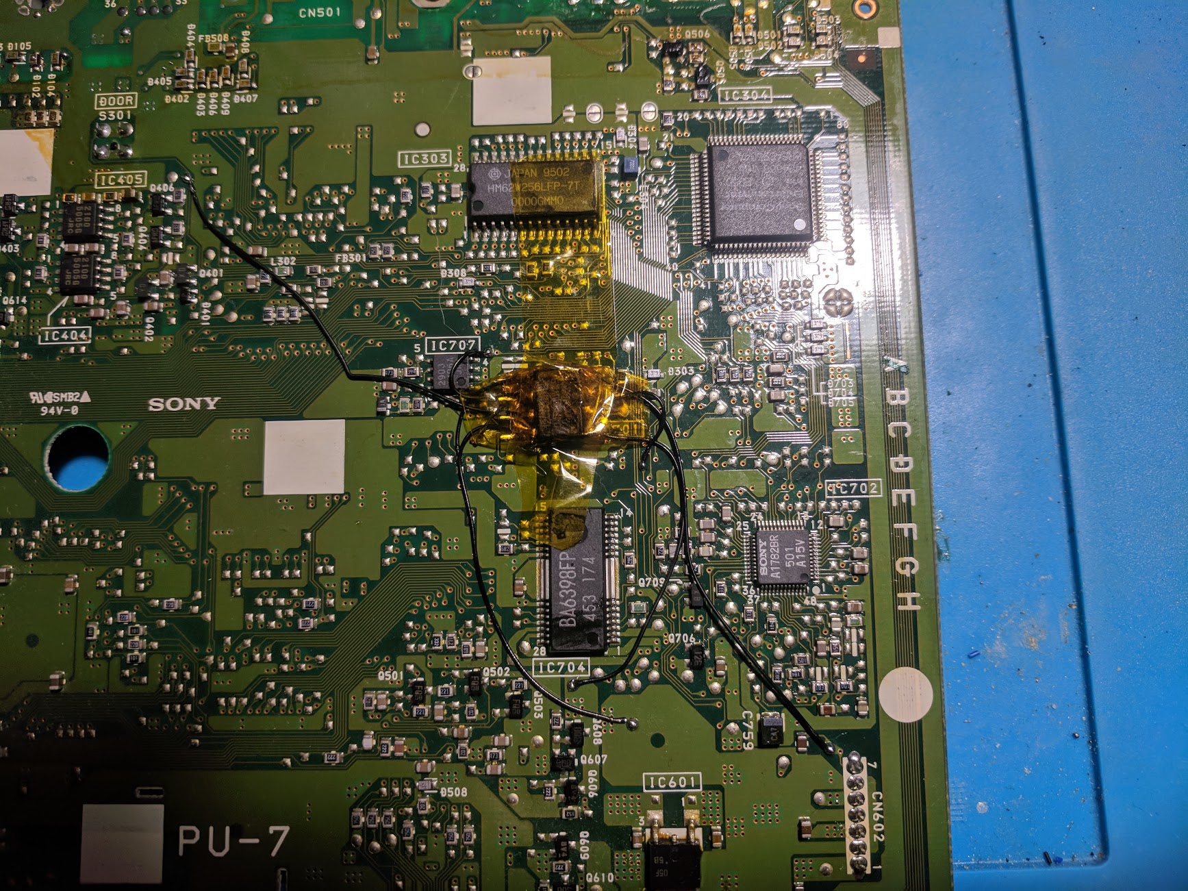
Hi, I’m Traace (Techflo) the Author of this picture. 🙂
William if you like to chat don’t hesitate to write me a mail.