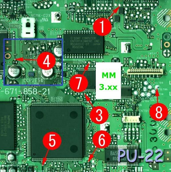
PU-22 MM3 modchip installation diagram
This is my favorite version of the PlayStation 1. It’s in newer systems, so the lasers are more likely to still be in good condition, but the system still has both the serial and parallel ports on the back. This board was used primarily with the SCPH-7500 series of systems.
For more information about MM3 chips click here, for more information about PS1 modchips click here.
PU-22 MM3 modchip installation diagram
Above is the diagram for the PU-22. Pin four is located towards the top left side of the board.
This diagram is fairly straightforward. There aren’t really any tricky points, or surface mount components you need to solder to.
Installation tips
Here are some tips I have for you when you are soldering your chip into the PU-22.
- Cut your wires to be as short and direct as possible.
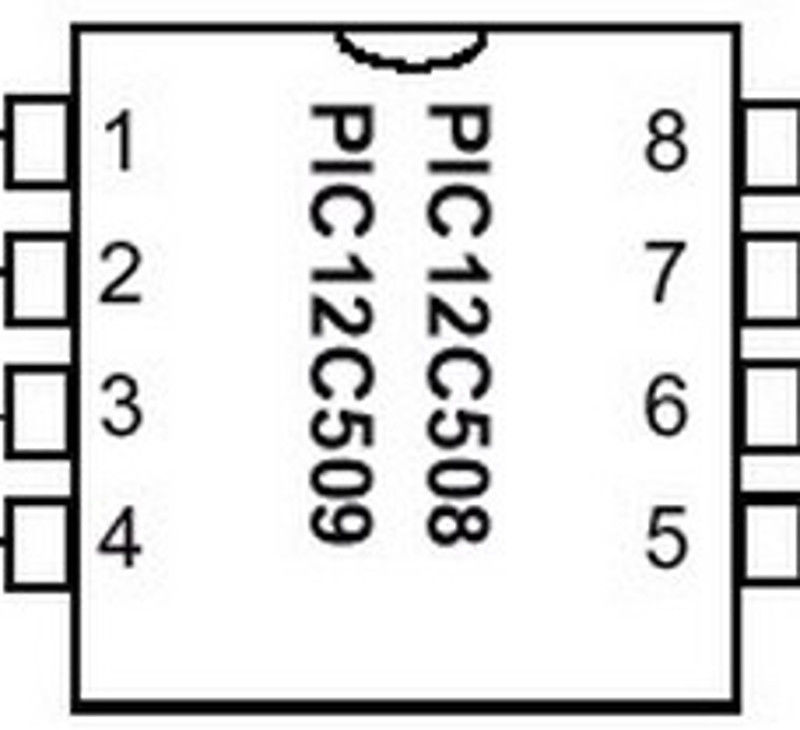
- Don’t connect pin two of the chip to anything.
- Pin 4 can either be connected to the pin 4 location in the diagram, or pulled high by connecting it to pin 1 on the chip.
- Watch out for solder splatter when you are desoldering the metal shield on top of the board.
- Placing the chip where the pin seven circle is seems to be the ideal location.
Example installations
This section has photos of some successful installations which you can use to get a better understanding of how everything is wired and positioned.
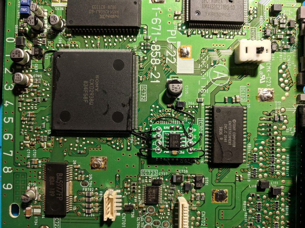
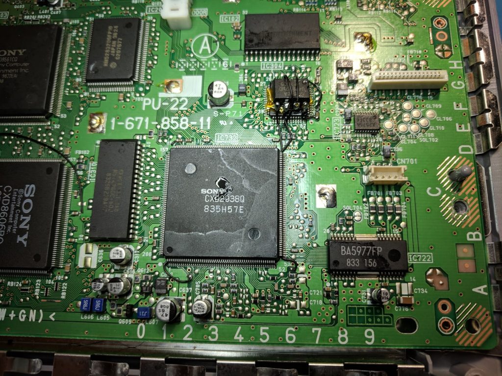
Here are some sample installations I have done in SCPH-7501’s:
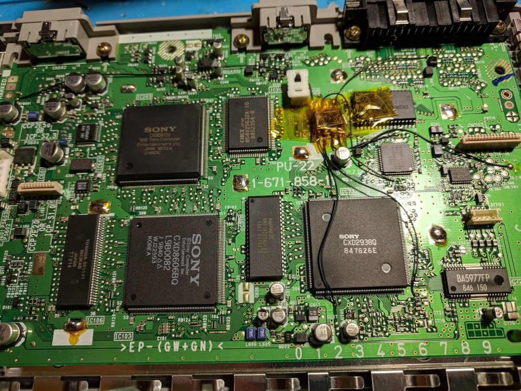
This first images show a cleaner way to install the chip with six wires. I probed the board with a multimeter to find alternate points to solder the wires to that are much closer together. I use the capacitor to the right to get the VCC and GND (pins 1 and 8) connected to the chip with really short wires.
Below is a messier installation using the diagram at the top of the page.

after installing my modchip, i tried to load a backup but am greeted with this screen below, im not sure if its a bad disk drive or not though, my ps1 model is SCPH 7502 PAL
Generally that’s a sign that the laser is worn out (or the backup isn’t the greatest quality).
Used the standard long wire diagram for a 1998 7501 console pu 22 board and got it working first try thankfully. Diagrams were great and your pre-programmed mm3 chip worked perfectly. Tip to others: pre tin wires and your board contact points so all you have to do is fuse them with a quick but deliberate touch, and don’t be afraid to use 30 watts to avoid cold bonds. My board was also lacquered, so be sure to clean the sites you need to solder thoroughly with alcohol and Q-tips until they shine.
I’m guessing I don’t need to put the metal shield back?
I put the shield back on when I mod systems, but it isn’t completely necessary.
Today i modded my new ps1 fat from eBay with this Diagram! However It seems like The Chip Doesnt Work properly I Can Start a Backup of ntsc dino Crisis only – Original Games dont load and a pal Backup of resi derectors cut doesnt start also My questions: The chipped ps does not Play Original pal Games anymore? Why? It should do so, Right? Why does The ps Play a ntsc Backup But no pal Backup? The Chip should Play both types! Where does This cracking stucking sound playback come from within of an Intro of a game? Too… Read more »
I think your laser assembly May be a little bit tired.Try another laser assembly, or cheap chinesse replacement. Túry read fine byť ste a little bit nikdy.
what is my problem if i can play originals and pal copies but no ntsc games with my chipped ps?
PAL SCPH-101’s (PM-41 or PM-41 (2) boards) have an additional region lock which prevents out of region games from playing, unless a ONEchip is installed. It could also be a problem with the TV not being able to display NTSC video.
If it can play PAL game backups then the chip is probably installed correctly.
Hm the board is pu-22 1-671-858-21 wired like the the diagram shows
Is probably number 1 in the diagram for the ntsc region?
I guess that one soldering contact isnt right then…with a ntsc backup the cd player menu pops up, tv works fine.
I also have a boot cd and i can run ntsc games with it but i dont want to use it because its obviously chipped :/
Pin #1 is to power the chip, regardless of its region. If you email me pictures of your installation (liam@quade.co) or reply to this with a link to pictures (using Imgur or something) I can take a look at the soldering. Again, if it can play PAL game backups then there isn’t really a reason why it shouldn’t be able to play NTSC game backups.
its an mm3 chip inside
Worked for me on my 22!
Why isn’t pin 4 required? I think pin 2 is for non-stealth firmware (rough google) but why not 4.
2 is for the clock pin, but only for Mayumi chips. For MM3 I believe there is a way to hook up an LED to pin 2.
4 is the one used to switch between modes using the reset button. It was useful for older chips that didn’t support stealth mode to play anti modchip games. Since the MM3 can play every game there is no need to use the reset button to disable it, so no need for pin 4.
Followed the instructions and installed MM3 to my original PlayStation from my childhood. Thanks very much.
Is it ok to clean the motherboard with rubbing alcohol? I just want to clean a little residue
Yes, the higher the percentage alcohol the better. I always clean the flux off of the points I solder to when I’m done.
Hello I need help. When I turn on my playstation there’s no display. The spinner isnt running but the laser on the cd spinner is on.
Look around the board for any possible solder that could have splashed somewhere it shouldn’t have.
Also make sure your wires aren’t too long (they need to be as short as possible).
Hi there, thanks so much for posting up this guide I’m looking to try installing the modchip using a tidier method. I’m thinking, could I solder directly to the motherboard’s respective chip legs instead of their pads? Say for pads 7, 3, 6, and 5. I’m thinking if I simply follow the traces back to their corresponding motherboard chip leg, could the modchip still work (provided I use good technique and a fine solder tip). I’ll basically follow the pad back to the leg by eyeballing the trace in between them first, then confirming with a multimeter. To this end,… Read more »
Soldering directly to the chip legs won’t damage anything (unless you bridge solder across the pins on accident). For pins 3 and 7 it’s a fairly easy thing to do. They connect directly to the mechanism controller chip (the one closest to the points in the diagram), it’s not too difficult to solder to these pins if you have experience soldering. For pins 5 and 6 things are a little bit different. They connect to one of the larger processor chips (right next to where the pins are in the diagram). It’s possible to solder directly to these pins, but… Read more »
Hey, so i installed the prewired chip i purchased on ebay. Now my ps1 boots fine to the no disc menu, but the drive never stops spinning, like it cant focus. Left the top off and it seems like the drive sends the laser out as far as it can but never finds anything, physically moving the laser just sends it back out. I swapped it out with another drive from another 7501 that was verified working and it does the same. Both of these drives worked before hand so im not sure whats going on. I double checked my… Read more »
Shorten all of the wires to be as short as possible.
Hey there, just recently installed the modchip, thanks very much for the guide! It’s been working with nearly everything so far but it doesn’t want to load Pop’n Music 2 (NTSC-J), any time I try to play it I get the anti-modchip “software terminated” screen. Everything else works perfectly including other NTSC-J games and Spyro 3 (PAL version) which I had heard had anit-modchip protection programmed in. Is this a compatibility issue with the MM3 itself or should this game work fine and this suggests that there’s something not wired up correctly inside? Thanks for your time.
Some extra information: I’m using a PAL SCPH-7502 model PS1. I’ve done a few more tests with other games, NTSC-U Crash Bash also works fine but Dokodemo Issho does not. It seems like Japanese games with anti-modchip screens are the problem, although I have managed to run NTSC-J Crash Bandicoot 3 without any issues.
It may be an issue with the installation. Make sure your wires are as short as possible, and that you connected all of the pins in the diagram at the correct location. I’m pretty sure some games have several versions out there. Some earlier versions didn’t have the anti-modchip code, and later versions did. That could be one of the things you are running into. It’s also possible that if you are downloading backups some of them could already be pre-patched (so that the anti-modchip code is removed), and others aren’t. If one anti-modchip game works with the modchip then… Read more »
Nice!
The install images showing the numbers are quite small and grainy but the clean PU-22 installation with short wires using alternative solder points is nice and HUGE even if it’s not that easy to see the hook up.
Would be really nice to get an image where an old man can clearly see where to solder wires…
Yeah, I’ve been meaning to make my own diagrams using a higher resolution camera but haven’t gotten around to doing all of the boards yet.
Hi there I have a couple questions. I’ve got the pu22 with a modcip installed. However there’s a couple of broken/ripped contact points. So if we look at the pic with the Sony cxd2938q just under it there’s a solder point where you have wired part of the chip (just above number c637 has a little trace to the CPU (think it’s the CPU) leg that one is broken off with the copper so all I have left is the trace….. The other point broken is the one just just below number 53. My question is can I straight solder… Read more »
Yes, you can solder directly to the CXD2938Q chip. Just be careful because it’s fairly easy to bridge solder across the pins on that chip since the legs are so close together.
Hello William! This was my first time soldering anything ever! and i feel it went well. with pre-practice and your instructions. So at this point when i try to play a burned game, sometimes it goes to the default ps1 menu, other times itll make it to the black ps1 screen, a few times its gone to the default ps1 menu then after about 10secs it goes to the black ps logo screen then does nothing else, and once it even ALMOST loaded the game up. made it to the first screen past the black ps1 one, and then froze.… Read more »
That behavior is common if the laser is worn out (or the disc burner and disc media combination isn’t creating a great backup). Burned discs are harder for the system to read so a system that can read retail games just fine might have some trouble loading backups.
So I swapped out a laser from my other ps1 and now it works perfect! You’re a legend man. I really appreciate everything you do!
Unfortunately i overheated contact point 6 but was able to solder directly to the board mounted capacitor, watch for splash & shorts, reinstall the heat shield, All good playing my most of my backup CDs I think I need a new laser
hey will, i’m making a website covering PS1 modchip installs, among other things. I do them voultar-style though, so the guides are a bit harder to follow but the resulting mod is much cleaner. I have this guide:
https://retrofreedom.com/ps1pu22.html
What do you think?
Looks great. Having the alternative points are also nice for people who may end up lifting pads when installing.
Hello William, nice of you to put a well documented guide here, i appreciate that 🙂 However, i seem to have run into a problem. I bought a MM3 chip from ebay for my SCPH7502, and followed your guide, up until i got to the solder-point number 6 on the board. There doesn’t seem to be any metal in this spot that i could solder the wire to. (sorry for my weak terminology lol). I don’t know if this PSX has been chipped before, but all of the other solder-points were untouched. My question is: Is there an alternative solder-point… Read more »
Maybe you’re looking at the wrong spot or something. If you look at some of the higher resolution sample photos you can see that point 6 also connects to the left side of the resistor directly below the point in the diagram.
Worked perfectly for me, I placed the chip over the “A” on the motherboard with double sided tape. Thank you!
Wth I was trying to be super delicate and I’ve done tons of 9001s and 101s, but on this 7501 I got all the traces just disintegrated
Yay I finally got a chip installed with the long wire points. I had killed 3 PSOnes before this so I decided to try an older model and it worked! The first time I had taped up the wires a bit and put the metal cage back but it didn’t even turn the disc spinner on. So I took it back apart and shortened a couple cords and redid the couple of points I wasn’t sure about and then left the tape and the cage off the 2nd try and it loaded the games up flawlessly! I do get a… Read more »
Hi William, Thank you so much for all your work. You make things so much easier for us green hobbyists. I really appreciate all the work you’ve done. Im getting ready to mod my ps1 with your information, here, and I have a question about the process. I’ve discovered that my PS1 is a PU-22 SCPH-7501. In this diagram, you’ve listed two different PIC’s but did not mention the ones I have on hand. I do see that you listed them (PIC 12F629) in the very beginning of the installation guide, but its not mentioned on this page, so I’m… Read more »
Any chip you can find a hex file for will work. 12F629 is one of them.
Working well on 7502 (PAL), chip 12C508A programmed with K150. William, thanks a lot !!!
Having trouble with a PU-22 MM3 mod, It only seems to read whatever disc I put in as an audio CD, official or backup.
Could potentially be a worn out laser. Sending a picture of your installation would be helpful.
Hi there,
I have managed to destroy the trace on the board that point 5 goes to. It’s a really short trace to a solder pad. I’m preparing to lift the pin on the chip and repair it with wire, but I’m really struggling to see where that solder pad went to, it looks like it just disappears? Can you help?
It connects to one of the pins on the large square chip above point 5 (to the pin where the trace disappears at). Click on some of the higher resolution example installations and you can count which pin it is.
Thanks so much for replying. I know I can solder the mod chip directly to that leg, but I’m worried about the existing trace being broken. I’ve destroyed the trace and that solder point. Are you saying if I solder the mod chip directly to the leg of the chip I don’t need to worry about that original trace?
Yes, it’s probably fine.
Thanks for the reassurance, I connected pin 5 by lifting the corresponding leg on the CD-ROM (I guess?) chip and it works fine 🙂 I really am curious as to what that small trace and solder point is for though. Do you think its more or less unused?
They are test points for when the system was made.
I bought from aliexpress a modchip 12c508 12c509
here is the link
https://www.aliexpress.com/item/32862535900.html?spm=a2g0s.9042311.0.0.bdff4c4dqH9gGK
I want to ask is the modchip I buy is the mm3 modchip?
Thanks
I don’t think so, not enough wires are connected. There are also three regions for most PS1 modchips and they only list two which is kind of weird.
Do you have a link on where to buy mm3 modchips?
Thanks
https://quade.co/store/ps1/mm3/
I just installed the chip and put my PlayStation back together, it turns on and outputs video but will the disc drive does not rev up. I’ve tried checking my connections and manually holding down the button which tells the ps1 the drive is closed, but it won’t rev up.
You probably messed something up. Blown fuse, short, super long wires, wiring to the wrong place, mixing up wires (mixing up 5-8 is common).
I’ll check over the wires and see if I can find any shorts. I’ll also try removing the chip and see if its my ps1 but it was working before.
Thank you very much for this guide!
I used it today to mod my PU-22 SCPH-7502.
It was a bit tricky to solder all the wires to the motheboard, but in the end, I’ve managed to do it.
Now it’s working great!
Yesterday arrived here in Germany. Immediately installed and very happy with it
https://www.instagram.com/p/CGDk-rKpjf8Nd0a9tt5e3IxI5tbWosOL70j8Rw0/?igshid=1v83tt9e1xjcj
Hello! First off, thank you for this incredibly detailed site. I am very grateful for it! I ordered a couple of chips off you awhile back, and only today had a chance to install one (on this pu-22 board). Everything seemed to go very smoothly, since these directions are very clear. When I tried it for the first time, though, it did not read the burned disc. I did test an original game, which worked just fine, which leads me to think that it is one of two things, but I could be wrong: A problem with my burn. I… Read more »
It’s generally an issue with the backup (as in the backup being burned to the disc, since usually the disc images are fine). Trying different CD media, write speed, and disc burner combinations can result in better or worse backup images.
Backups are harder to read than genuine discs. If you get an import and it works then that means that the chip and install are both good, but your laser is worn out. If the import doesn’t work then it’s an issue with your chip or the installation.
Import incoming, thanks!
my ps1 is a 9001 made in march 2000 should i use the pu-22 guide or pu-23?
PU-23. If you take apart your system the board model will be printed on it.
I successfully installed an MM3 Chip in my PU-22 Playstation 1 with this guide, thank you very much!
is there another point for pin 6? the pad has lifted
If you look at some of my example installations (or your board) you can see that it connects through a small trace to the black resistor right beneath the original point, and then to a brown capacitor, and then to that big chip.
can i solder to the capacitor? i have the same problem with pin 3, the small chip is difficult to solder to
For pin 6 you can solder anywhere where that small line in the example installations connects (including that one side of the nearby capacitor).
thanks i managed to connect to the capacitor. what can i do for pin 3?
Pin 3 also connects to the top side of the middle black resistor directly below the point in the diagrams. The board probably won’t work if you lifted that pin 3 pad and broke the trace.
i have repaired the trace and the disc spins again but if i connect pin 3 it won’t spin
Just prepping my 7501 for this install. I fear that none of my irons have a fine enough tip, but I’ll do my best. Thanks for the detailed guides. It’ll be nice to finally quit disc swapping after all these years.
Just did the install and everything works perfectly. Eliminated all the audio issues I was having while swapping discs as well, so that was a welcome bonus. Thanks again.
hello, i’m pretty sure i destroyed the pad for pin 5, any alternate points i can use?
i don’t really wanna try to solder to the bigger chip above it, the legs are too close together and i know i’ll probably fuck it up bad. 😅
That bigger chip is the only alternate point for pin 5.
ayy mama, well… guess i’ll give it a try.
Anyway, thank you for your reply and all the guides also, i succesfully modded the 5502 of a friend following your instructions.
Hey! I followed this guide and it did not work, My ps1 can power on but the disk drive does not spin and I get no display, What should I do?
Check for shorts and blown fuses.
I have PIC16C711-04/P
but yellow wire disconnected…
I don’t know where to put it
I’m not sure what modchip that is, and that doesn’t look like a PS1 (this page is for PS1 consoles). Maybe try asking in a PS2 forum.
I got a problem i finished this mod. But my ps1 don’t give out any picture and drive isn’t spinning. The power button still glows up.
You messed something up. You probably should remove the modchip and check for shorts or blown fuses on the PS1 board.
I remove the chip the PlayStation won‘t boot anymore.