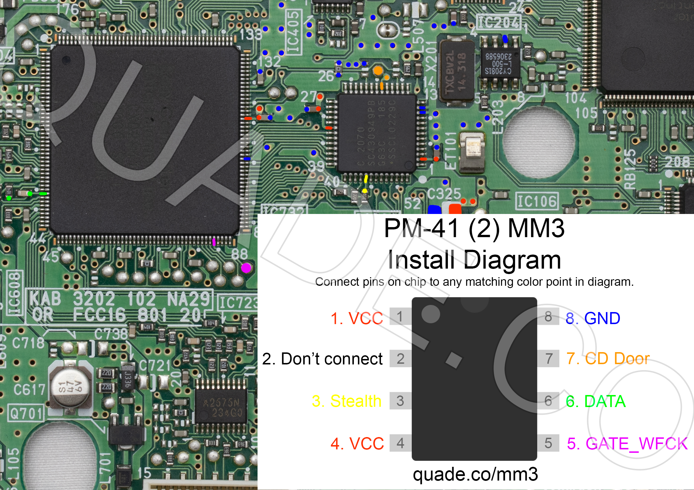
PM-41 (2) MM3 modchip installation diagram
Towards the end of the SCPH-10x PSone production Sony revised the board slightly and released the PM-41 (2) board. This page covers the installation diagram for installing an MM3 chip into the PM-41 (2).
If your board has PM-41 printed on it then you should follow the PM-41 guide instead.
For more information about MM3 chips click here, for more information about PS1 modchips click here.
The first time I modded a PM-41 (2) I wasn’t able to find an installation diagram, but was able to figure out how everything should be wired through a combination of trial and error, and the diagram for the original PM-41 board.
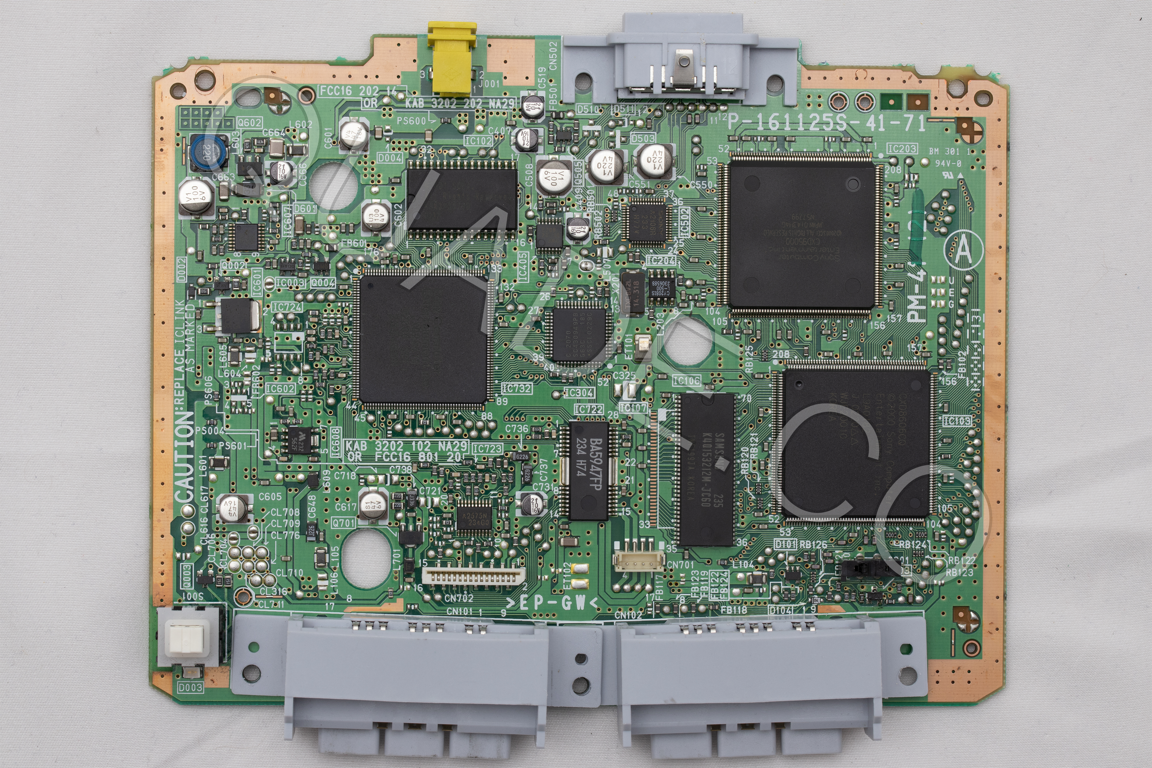
PM-41 (2) board components and fuse locations
Here are a couple of photos of the PM-41 (2) board. If you click on them they’ll open in a much higher resolution format so you can zoom in on the details. This first image shows the front of the board (marked with the letter A).
This second image shows the back of the board (marked with the letter B).

Below is that picture of the front of the board again, but this time it has labels on all of the major board components. This can be useful if you are debugging an issue on the system. For example if your video output is bad you might want to try replacing the capacitors near the video amplifier.
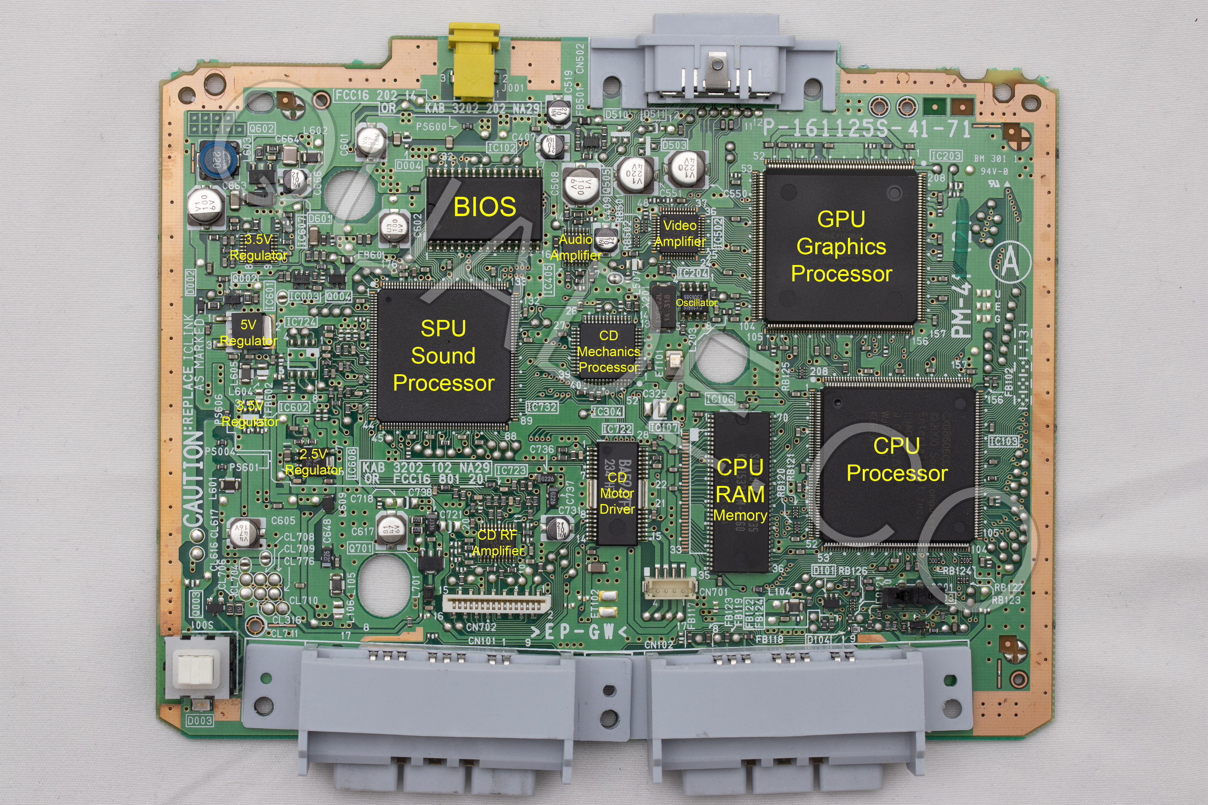
Another common issue people run into is blown fuses. Below is a diagram showing the locations of all of the fuses on the PM-41 (2) board. They are highlighted in yellow, with the fuse value nearby.

PM-41 (2) MM3 modchip installation diagram
Above is the installation diagram. Just match each colored pin label in the diagram with any matching colored point on the board. Click on the image for a higher resolution version. I recommend placing the modchip on top of the CD mechanics processor chip.
I have created additional diagrams primarily for colorblind people. They show one point at a time in a single color (there is a set in red, green, and blue). Because they show the entire board they may reveal more alternative points for each pin. Click on the links below to reveal the sets of images.
I’m creating these new diagrams for each PS1 board revision working from newest revision to oldest revision. It’s going to take some time, but should hopefully be more helpful than the older diagrams I had on here before.
PM-41 (2) MM3 modchip installation diagram (one diagram per pin, colored in red)
Click on the images to see them in higher resolution.
VCC: Pin 1, Pin 4

Stealth: Pin 3

GATE_WFCK: Pin 5

DATA: Pin 6

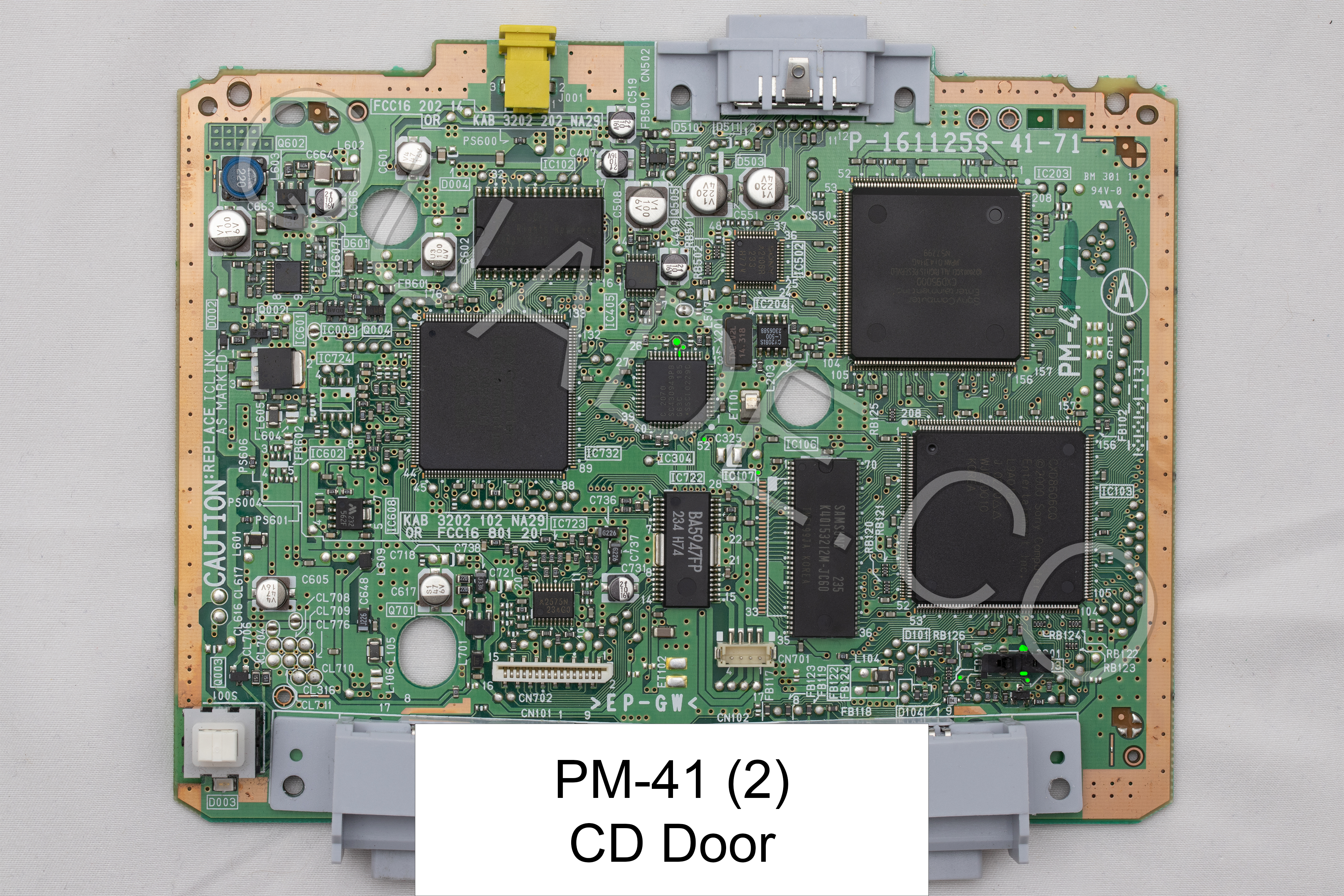
CD Door: Pin 7

GND: Pin 8

PM-41 (2) MM3 modchip installation diagram (one diagram per pin, colored in green)
Click on the images to see them in higher resolution.
VCC: Pin 1, Pin 4

Stealth: Pin 3

GATE_WFCK: Pin 5

DATA: Pin 6

CD Door: Pin 7
GND: Pin 8

PM-41 (2) MM3 modchip installation diagram (one diagram per pin, colored in blue)
Click on the images to see them in higher resolution.
VCC: Pin 1, Pin 4

Stealth: Pin 3

GATE_WFCK: Pin 5

DATA: Pin 6

CD Door: Pin 7

GND: Pin 8

Installation tips
Here are some tips I have for you when you are soldering your chip into the PM-41 (2).
- Cut your wires to be as short and direct as possible.
- Don’t connect pin two of the chip to anything.
- Pin 3, and 6 can be tricky. Don’t push on the components with your soldering iron or they might get knocked off the board. You can use tweezers to carefully solder them back on one side at a time, the orientation doesn’t matter.
- Make sure the wire on pin 3 and 6 don’t come into contact with both sides of the component (this is especially common if you run the wire directly on top of the component).
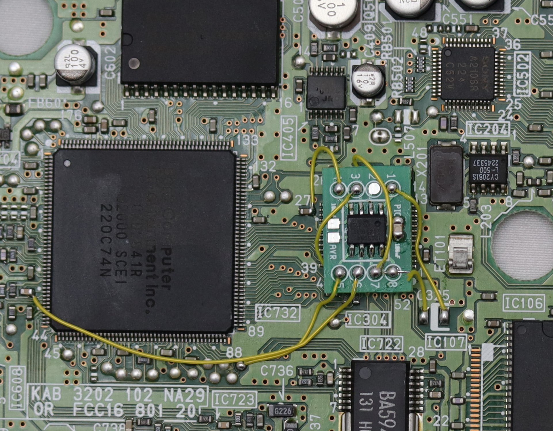
Example installations
This section has photos of some successful installations which you can use to get a better understanding of how everything is wired and positioned.
Here is an example installation have done:
I just installed the MM3 I bought from you on ebay on a PM-41 (2 ) board. It works great. Tiny amounts of solder and a gentle hand with the iron made for a successful first attempt. Thanks for hooking me up.
Attempted my first ever mod chip installation with this board today. I bought some of your pre-wired chips off of ebay.
Man, some of those soldering spots are so tiny. But fortunately I got them all in place according to the diagram and it worked great!
Tomorrow I’ll attempt console #2.
Awesome. Good luck on your second system.
hello!
i have got a problem: i soldered like the diagram shows but it doesnt work somehow…how do I have to solder pin 3 and 6? should i get them off at first?
You can email me some pictures of your installation (liam@quade.co). Pins 1, 3, 5, 6, 7, and 8 are all required. Make sure your wires are as short as possible and that you didn’t switch around any of the pin numbers on accident.
unfortunately it is too late – my psone-board is already broken. my problem was to handle pins 3 and 6: at first i soldered the wire on top of the resistors but that didnt work so i tried to get the resistors carefully off the board but then it suddenly flew away (even handeled with a tweezer) and i didnt find it back again. it is too tiny to find. the other resistor even broke as i tried to get it off the board – soldering to all other points was successful and easy but those damn tiny resistors killed… Read more »
Hi guys I purchased one of the chips for my psone schp-101 and the number 3 resistor or whatever it is come off and I’m having a hard time getting it back on. Any suggestions? I have the chip still just can’t get t to stay in place.
Here’s a video showing somebody soldering a larger resistor back into place: https://www.youtube.com/watch?v=_DsCdOaRUPM
The same process works with smaller ones like with the one in the PS1. Before you start you’ll probably want to clean off the solder already on the pads with some wick, just be careful so you don’t rip off one of the pads.
Hi William. I have SCPH-103 with 12C508/P 04 SAW 0449 installed. Couple days ago, I decide to replace the old optical laser because is to weak read disc with new one I bought online. But accidentally, when I want to put it back together, one cable from pin 2 has disconnected from mainboard. And when I turn it on, I can’t hear psone sound from TV just a white screen with PS1 orange logo. I take my psone to local service center, and the guy on the store tell he forgot psone wiring but he do soldering and it not… Read more »
I’m not sure what modchip that is and can’t find a matching diagram
The place you soldered pin 2 to and the positioning of the modchip likely wouldn’t work even if it were the correct point. It’s a clock line and with that length of wire you’d run into issues.
Try completely removing the chip and seeing if that allows the system to boot. There could also be a blown fuse somewhere. You can test the fuse components labeled PS# on the board with a multimeter.
Hello just got done doing a mm3 on psone scph 101 and it will not power on or soon disc. It only powers on when you pull up on the power cord still does not spin. Any ideas on what that could be?
It could be that the solder connecting the power socket to the board is cracked and needs reflowed. It’s also possible you blew a fuse or something.
Hey just wanted to say I just tried the new Point 5 and it works perfectly. Thank you so much. This is my 2nd system I’ve modded with your site. I placed the chip between the 2 chips on the diagram and my Point 4 is connected to Point 1 and I used the large points right above the “41” on the Diagram Key for Power and Ground (1 and 8) and I was able to keep all the wires short except 6 and 7. I have really good boots tho and it is way better than the fat model… Read more »
Queria saber qual peça é responsável pela vibração doa controles..pois o meu psone slim parou de vibrar..desde já agradeço
I’ve got a pm 41 (b) and confused which instructions I should follow.
If it doesn’t say PM-41 (2) then it’s not this one, it’s as simple as that.
Accidentally knocked off one of the 220 resistors on pin 3, I think that it might be dead because it doesn’t work when reconnected, any idea of some quick fixes I could do or components I could buy?
Replace the resistor with another one, that’s the only way to fix it.
Do you need a flux? I don’t know how to solder wires in motherboard. Do I just solder both points I’m connecting together first or put the wire on the motherboard and then solder
You’ll want to use flux. It isn’t completely necessary but you’ll probably get really bad results if you don’t. Just connect the wires from the point on the board to the chip. You can start with the wires on the board, or on the chip, doesn’t matter which order (I solder the wires to the board first, then solder them to the chip).
The diagram looks good. Like Nathan said, I think the Pin 4 adjustment should be mentioned in the instructions.
Also I’d like to know what the red dots are for. they were a bit confusing and I saw them on other diagrams.
Speaking of other diagrams I’ve seen one where pin 3 is one resistor over incorrectly (?) It looks like you adjusted the diagram because of that, but I think that shoud also be mentioned in the instructions.
Yeah, I went ahead and updated this page. I’m not sure where the red circles are from. The one at the very top could be an alternate positive voltage or ground connection for pin 1 or 8 on the chip (I’d have to measure it to know for sure). The other one doesn’t even have any arrow or anything.
The incorrect pin 3 problem is in a ton of diagrams. I really try making a cleaner diagram from scratch the next time I have a PM-41 (2) board available.
Is pin 5 correct in the above diagram? Every other wiring chart I’ve seen has it placed a few solder points left, including the photograph you give as an example.
Yes, pin 5 in the diagram above is correct. It doesn’t not work in the other spot, but it will certainly work better in the spot in my diagram. See this thread for more details: https://www.obscuregamers.com/threads/psone-pm-41-2-a-modchip-problem.618/
What’s going on with the 4 pin in your picture? it looks like it’s soldered to the 1 pin
Yes it is. Pin 4 is used for the reset button on fat model PS1’s. So for the SCPH-101 that doesn’t have a reset button you can either leave pin 4 disconnected, or connect it to the positive voltage supply (which is pin 1 on the MM3 chip).