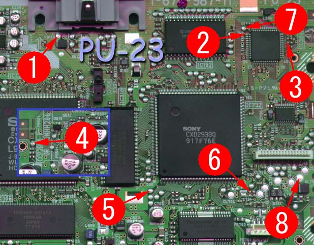
PU-23 Mayumi v4 modchip installation diagram
The last version of the original PlayStation 1 design was the SCPH-900x. Most of these consoles have PU-23 boards inside. The most notable difference between the 9000 series and earlier consoles is that Sony removed the parallel IO port on the back. They also shrunk down the size of the board significantly.
For more information about Mayumi v4 chips click here, for more information about PS1 modchips click here.
PU-23 Mayumi v4 modchip installation diagram
Above is the diagram for the PU-23. Pin four is located towards the top left side of the board.
Since the diagram isn’t the clearest I’d like to mention that the second pin connects to the top most pin on the left row of pins on the chip. Pin three connects to the left contact on the middle resistor, and pin six connects to the top contact on the left capacitor.
Installation tips
Here are some tips I have for you when you are soldering your chip into the PU-23.
- Cut your wires to be as short and direct as possible.
- The high speed clock line (pin 2) needs to be especially short and carefully routed.
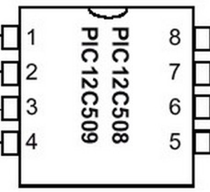
- Pin 4 can either be connected to the pin 4 location in the diagram, or pulled high by connecting it to pin 1 on the chip.
- Pin 3, and 6 can be tricky. Don’t push on the components with your soldering iron or they might get knocked off the board. You can use tweezers to carefully solder them back on one side at a time, the orientation doesn’t matter.
- Make sure the wire on pin 3 and 6 don’t come into contact with both sides of the component (this is especially common if you run the wire directly on top of the component).
- Don’t apply too much solder to pin 2 or you’ll bridge the pins on the chip.
- Placing the chip where the pin two circle is, or below it, seems to be the ideal location for placing the chip.
Example installations
This section has photos of some successful installations which you can use to get a better understanding of how everything is wired and positioned.
It was a close one! I knocked the piece off of where pin 6 goes, but I got it back on and the mod works! Thanks!
https://imgur.com/F0sderM https://imgur.com/VaU83TA https://imgur.com/1PC1Tgh https://imgur.com/uN2tJ7g https://imgur.com/OnthNoo Hey I’m back, I decided to take this 12c508p chip I was working on the PM 41 (2) board and install it on another ps1 scph 9001 PU 23 board, see the pictures in the links, it is not working, and well, i didn’t exactly follow this diagram because I followed this install guide https://www.youtube.com/watch?v=IUOjJB_naqc&fbclid=IwAR2hLZ70_JFBjds8Yv6kHrwxocSAA0c4pfII25jcW05V-Faf8_AhozAN4jw … which only differs in the location of pin 4, now i’m being told that i might have killed the chip by heating it up far more cycles than the limit, i’m new at this so i was not thinking… Read more »
Yeah, those wires are way too long. They need to be as short as possible. This is especially the case for the Mayumi v4 chip (pin 2 in particular, make that the shortest).
The location of pin 4 in the video is fine.
The chip is probably fine. They are designed to be soldered so they can withstand a lot of heat.
I’ve absolutely never had an issue with MM3 and I’ve got the hex files for basically every chip released since Old crow. (Well there’s some new ones out now I just found out about) but I’d like to try a Mayumi just for fun. I will see if I can wire leg 2 direct to it’s point with maybe a stub of heatshrink over it.
There we go, some of the points on the diagrams are a bit silly. Many alternates for most.
https://imgur.com/gallery/5cWpxTn