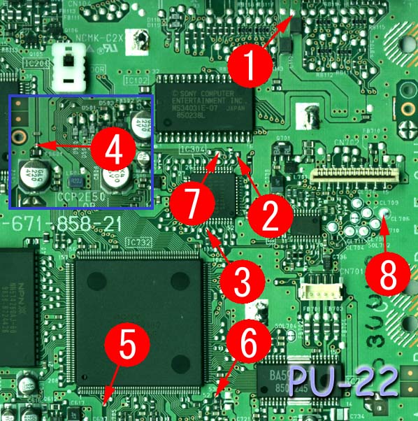
PU-22 Mayumi v4 modchip installation diagram
This is my favorite version of the PlayStation 1. It’s in newer systems, so the lasers are more likely to still be in good condition, but the system still has both the serial and parallel ports on the back. This board was used primarily with the SCPH-7500 series of systems.
For more information about Mayumi v4 chips click here, for more information about PS1 modchips click here.
PU-22 Mayumi v4 modchip installation diagram
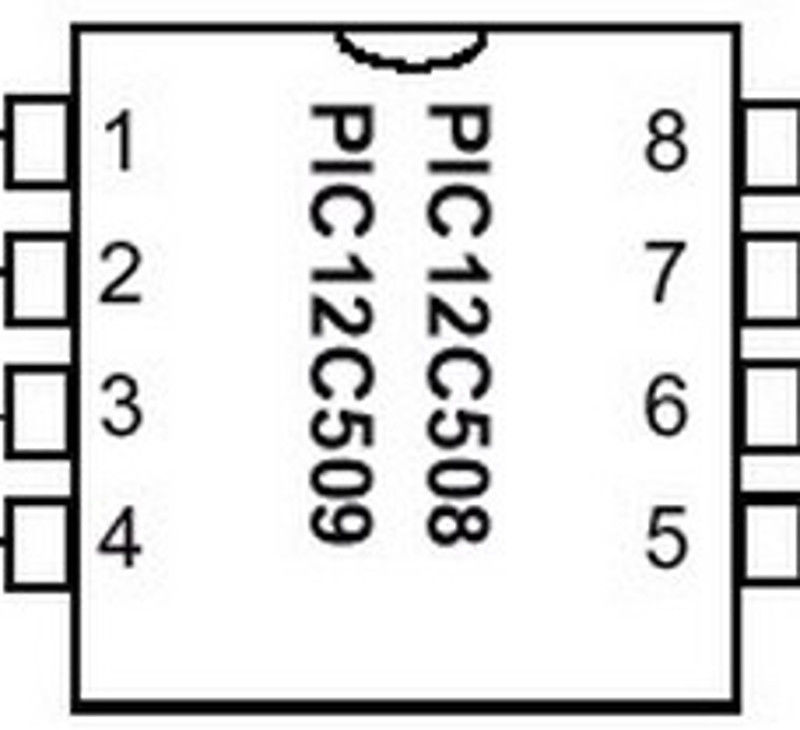
Above is the diagram for the PU-22. Pin four is located towards the top left side of the board.
This diagram is fairly straightforward. There aren’t really any tricky points, or surface mount components you need to solder to.
Installation tips
Here are some tips I have for you when you are soldering your chip into the PU-22.
- Cut your wires to be as short and direct as possible.
- The high speed clock line (pin 2) needs to be especially short and carefully routed.
- Pin 4 can either be connected to the pin 4 location in the diagram, or pulled high by connecting it to pin 1 on the chip.
- Watch out for solder splatter when you are desoldering the metal shield on top of the board.
- Placing the chip where the pin seven circle is seems to be the ideal location.
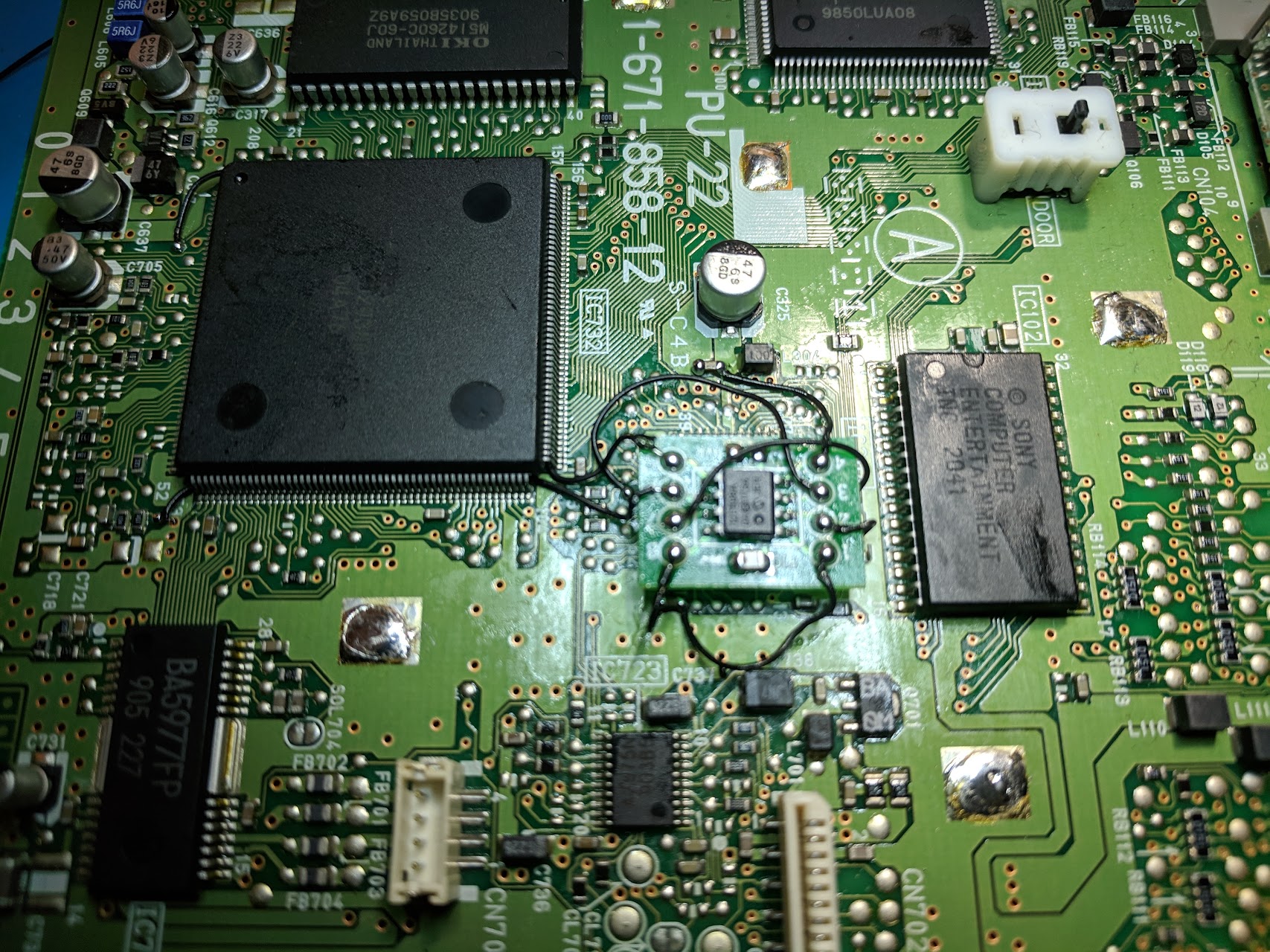
Example installations
This section has photos of some successful installations which you can use to get a better understanding of how everything is wired and positioned.
- William Quade (me)
I keep forgetting to post a pic of my install. Any tips for improvement?
https://imgur.com/EYMRz1b
Looks good.
I used your diagram to successfully wire up a SCPH-7501 PU-22. I should have taken a picture before putting on the metal shielding. I wired pin 2 of the chip directly to the motherboard. I did not connect pin 4 to pin 1, just to the regular pin 4 location.
Is There An Alternate Point for Wire 6 ? I Have Accidentally Removed The Solder Pad to That Point.
You’d have to solder a wire to one of the legs on the large chip above and to the left of the pin 6 (you’d need to follow the small trace to find which pin to use). It’s tricky to solder to those pins though since they are so small and close together.
Thank You. I Was Able To Solder It to The Nearest Capacitor Along That Trace Instead and It Works Great.
I also used this guide – cheers. The PU-22 was my backup PlayStation bought in case the other (a PU-18 model) mod failed. The previous owner had installed another modchip in it that I removed. But the pin 5 joint wasn’t too happy about being touched again, so the entire trace came off with the wire. Attached picture shows how I got around this.
Same thing happened to me. Desoldered pad 5(only the round pad) from the motherboard after removing old solder…… Isn’t there a way to remake a solder pad or to make the solder to stick again on the motherboard? I’m in no way able to solder the wire directly to the pin of the Sony chip…..
If you lifted the pad you’re pretty much out of luck. If there is still a trace left you can scratch away the solder mask on it and then solder to the trace, but realistically that isn’t going to be any easier than just soldering to the pin on the chip.
Damn…. Thank you.
I did it because I had little other choice. Not saying it was easy, or that I thought today was the day to try something I’ve only seen done by the YouTube solder-pornographers:D In my case the length of the trace just peeled off when exposed to heat. Figured connection to chip was my best bet. I fixed the wire between the caps using double sided tape. Added flux around chip pin that the trace ended at, tinned the wire, nudging back and forward, checking with magnifying glass (couldn’t see directly), then touched (!) it with tinned soldering iron when… Read more »
https://imgur.com/gallery/sxEP9qS
This is my first Mayumi Install out of curiosity (i have no issues with MM3)
I’ve tied the clock leg direct to the PSX mainboard IC leg with a tiny bit of heatshrink for insulation. This is a direct connection and also holds the chip in place. The rest is mainly alternate points for neatness.
In order to get pin 2 as close as possible, I flipped her on its back, spread its legs wide, and got pin 2 as close as possible to the board to run about 2mm of wire from the leg to the pad. Works perfectly. But note in order to get the chip this close to the pad and use minimal wire, you need to cut into the RF shield because if you mount the chip outside of the shield area, the metal CD-ROM plate will interfere with the chip. I used insulated tape just in case the console is… Read more »