PU-18 DFO installation diagram (dual frequency oscillator)
This board was used with a wide range of consoles from the SCPH-5000’s, and SCPH-5500’s, to even some SCPH-7000’s and SCPH-7500’s.
For more information about PS1 dual frequency oscillators click here, for more information about PS1 mods click here.
PU-18 DFO installation diagram
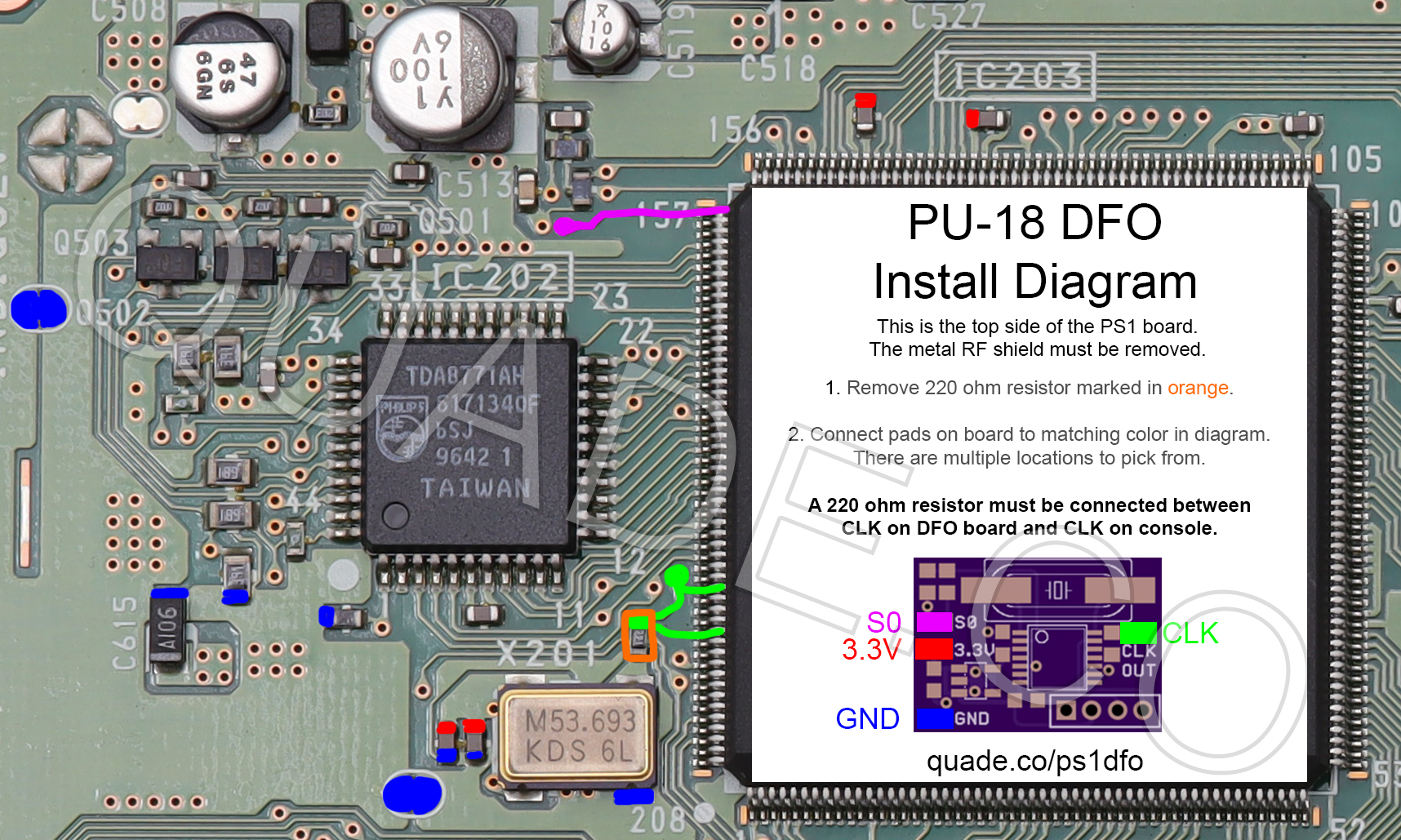
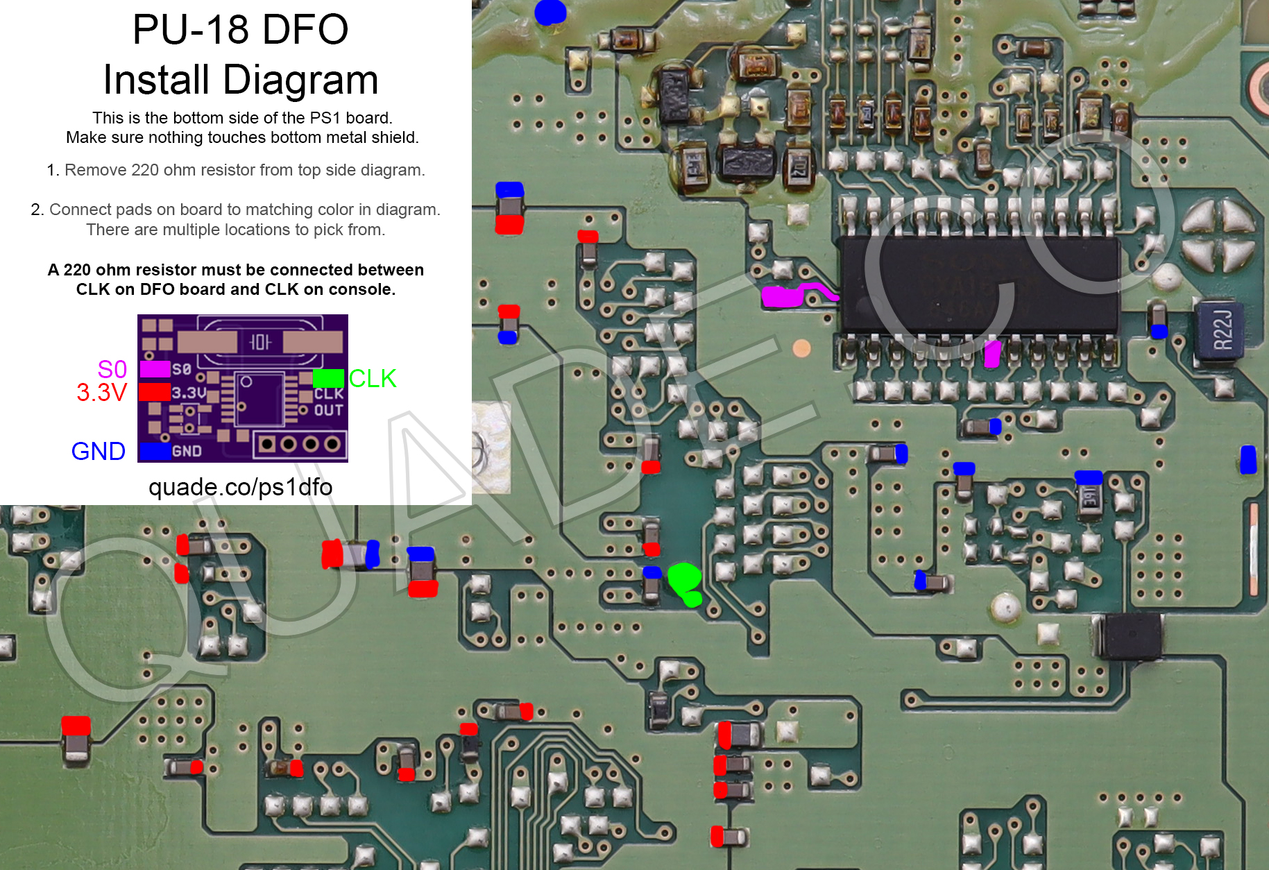
Below are two diagrams. The first one shows the top side of the console board. The second one shows the bottom side of the console board. You can install the DFO on either side. In either case you want to make sure the installed board isn’t making contact with any of the console’s metal shielding.
When installed on either side you will need to do at least some work on the top. The top metal RF shield needs to be removed, and the small 220 ohm resistor marked in orange needs to be removed. This will uncouple the onboard oscillator from the graphics chip.
If you are a beginner, or just looking for an easier installation experience, I’d say the bottom installation is a little bit easier. Installation onto the top requires soldering to a via hole for S0. When installing onto the bottom you can get away with only soldering to pads.
Click on the images to see them in a higher resolution.
Installation tips
Here are some tips I have for you when you are installing the DFO onto your PU-18.
- Cut your wires to be as short and direct as possible.
- Installation onto the bottom is a little easier.
- You can remove the 220 ohm resistor on the console by heating it up with a soldering iron. Quickly switch between heating up each side until it comes loose.
- If you have a hot air rework station you can remove the X201 crystal and use the onboard 220 ohm resistor. Remove the crystal, leave the 220 ohm resistor installed, and then connect CLK from the DFO to the crystal side of the 220 ohm resistor.