PM-41 (2) DFO installation diagram (dual frequency oscillator)
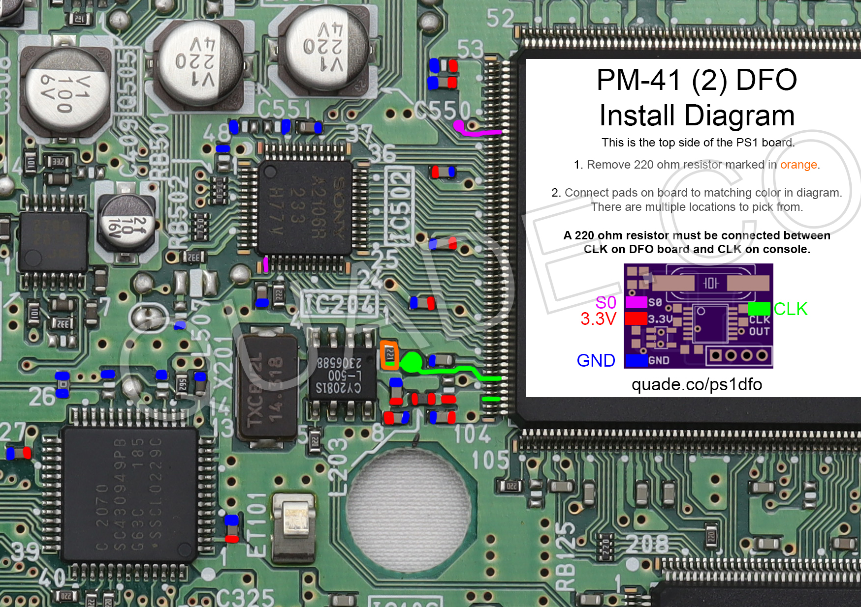
Towards the end of the SCPH-10x PSone production Sony revised the board slightly and released the PM-41 (2) board. This page covers the installation diagram for installing an MM3 chip into the PM-41 (2).
If your board has PM-41 printed on it (without the (2)) then you should follow the PM-41 guide instead.
For more information about PS1 dual frequency oscillators click here, for more information about PS1 mods click here.
PM-41 (2) DFO installation diagram
There is just a single diagram below. It shows the top side of the console board. It doesn’t really make much sense to try installing it onto the bottom side of the board because there isn’t really any space underneath the boards on slim systems. There are a couple of vias connecting the S0 points on the bottom side of the board. There are also a couple of vias connecting the CLK points on the bottom side of the board.
The small 220 ohm resistor marked in orange needs to be removed. This will uncouple the onboard oscillator from the graphics chip. You will also need to make sure that the DFO board isn’t making contact with any of the metal shielding on the console.
Most of the points are pretty straightforward to solder to. The one main exception would be the S0 line. S0 requires soldering to a leg of an IC chip. The good news is that it’s located on the corner of both chips so it isn’t too difficult.
Click on the images to see them in a higher resolution.
Installation tips
Here are some tips I have for you when you are installing the DFO onto your PM-41 (2).
- Cut your wires to be as short and direct as possible.
- Install onto the top side of the board.
- You can remove the 220 ohm resistor on the console by heating it up with a soldering iron. Quickly switch between heating up each side until it comes loose.
- If you have a hot air rework station you can remove the IC204 clock chip and use the onboard 220 ohm resistor. Remove the clock chip, leave the 220 ohm resistor installed, and then connect CLK from the DFO to the crystal side of the 220 ohm resistor.
- To solder to the leg of an IC chip for S0 you’ll want to pre-tin the wire and leg with a little bit of solder, and use flux. Soldering to the leg on the smaller chip should be a little bit easier.